CE 312 Lecture 25: Beam/Frame Deflections III, Probs. w/ Multiple Moment Functions (2026.10.16)
 Watch on YouTube →
Overview
Gregory Michaelson develops a virtual-work method for finding beam deflections and rotations when real and virtual bending-moment diagrams require different piecewise functions. For a 30 ft simply supported beam carrying 1.2 kip/ft, he derives the real moment equation, constructs two virtual moment functions for displacement at a point 10 ft from support A, and calculates a deflection magnitude of 0.792 in; he then sets up the rotation analysis using a unit moment.
Key takeaways
- For a simply supported 30 ft beam under a full-span 1.2 kip/ft uniform load, symmetry gives 18 kip reactions and a 135 kip-ft maximum moment at midspan.
- The real bending-moment function is M(x) = 18x - 0.6x² over 0 to 30 ft; checking its values at x = 0, 15, and 30 verifies the diagram.
- A unit vertical load 10 ft from the left support creates virtual reactions of 2/3 and 1/3, making the virtual moment function piecewise over 0 to 10 ft and 10 to 30 ft.
- The displacement integral must be split wherever either moment function changes; here the real moment remains continuous while the virtual moment changes at B.
- The example’s displacement calculation uses integral contributions of 3,000 and 8,000 and yields a magnitude of 0.792 in after applying the EI and unit-conversion factors.
- To calculate rotation at B, replace the unit vertical load with a unit moment, derive the resulting virtual moment functions, and use the rotation-specific conversion factor.
Chapters
0:00
Homework 6 Deadlines and Preparation for Multiple Moment Functions
- Homework 6.2 is due Wednesday; homework 6.3 and 6.4 are due Friday.
- Homework 6.3 requires only a screenshot showing that MASTAN runs on the student’s computer.
- Michaelson recommends graphically constructing the real and virtual moment diagrams before Monday’s lecture to get a head start on homework 6.2.
3:00
Virtual Work for Beam Deflection and Rotation
- Virtual work combines a real structural analysis under the applied loads with a virtual analysis using a unit force or unit moment at the point of interest.
- For beams and frames, integrate the product of real and virtual bending moments over the span and divide by EI; truss calculations instead use axial forces and EA.
- Real and virtual structures can have different numbers of moment-function intervals, so each diagram needs its own careful bookkeeping.
8:00
A 30-Foot Beam with a 1.2 Kip-per-Foot Load
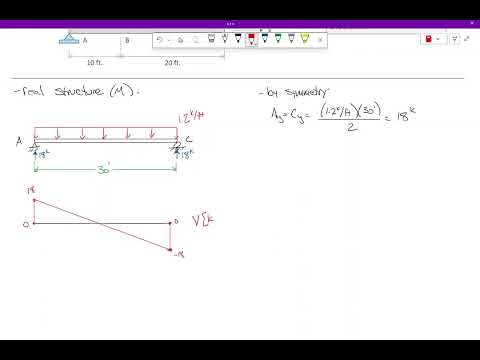
- The example is a simply supported 30 ft beam with a uniformly distributed load of 1.2 kip/ft; point B is 10 ft from support A.
- The load totals 36 kips, so symmetry gives reactions of 18 kips at A and C without a full statics calculation.
- Michaelson uses E = 4,000 ksi and I = 6,000 for the concrete beam, noting that lower-modulus concrete members need larger section properties to achieve comparable EI.
12:00
Graphing the Real Shear and Parabolic Moment Diagrams
- The real shear diagram drops linearly from +18 kips at A to -18 kips at C, with a slope of -1.2 kip/ft.
- The shear-diagram areas produce a maximum bending moment of 135 kip-ft at the 15 ft midpoint.
- The real moment diagram is one continuous downward-opening parabola, not two separate mathematical curves, with zeros at x = 0 and 30 ft.
18:00
Deriving and Checking the Real Moment Function
- A section cut from the left gives M(x) = 18x - 0.6x² for 0 ≤ x ≤ 30 ft.
- The quadratic form matches the graphical prediction, and its x² coefficient is negative as expected for a downward-opening parabola.
- Substitution confirms M(0) = 0, M(15) = 135 kip-ft, and M(30) = 0, providing three checks on the equation.
24:00
Building the Virtual Structure for Displacement at B
- A unit vertical load at B, 10 ft from A, produces virtual reactions of 2/3 at A and 1/3 at C.
- The virtual shear diagram has two regions, so the virtual moment diagram requires separate functions over 0 to 10 ft and 10 to 30 ft.
- Using slopes and known points avoids two additional section cuts: m₁(x) = 2x/3 on the first interval, and m₂(x) = 10 - x/3 on the second.
33:00
Integrating the Piecewise Functions for Beam Deflection
- The displacement integral is split at x = 10 ft because the virtual moment function changes there, while the real moment function remains the same across both intervals.
- With E = 4,000 ksi and I = 6,000, the calculation converts the foot-based integral using a factor of 1,728.
- The two integral contributions are 3,000 and 8,000; combining them gives a displacement magnitude of 0.792 in.
40:00
Applying a Unit Moment to Find Rotation at B
- For rotation at B, the virtual structure applies a unit moment at the 10 ft point; the supports still develop reactions to maintain equilibrium.
- Moment equilibrium gives an upward reaction of 1/30 at C and an equal downward reaction of 1/30 at A.
- The virtual shear diagram includes constant regions, and the applied unit moment creates a jump in the virtual moment diagram at B.
45:00
Rotation Uses New Virtual Moments and the Same Interval Limits
- The rotation calculation uses the new virtual moment functions for the unit-moment case, rather than the unit-load functions used for displacement.
- The integration intervals remain 0 to 10 ft and 10 to 30 ft, while the conversion factor changes because the target quantity is rotation.
- Michaelson leaves the rotation integrations as practice and recommends drawing the virtual moment diagrams for both homework problems before Monday.
Summary, takeaways, and chapters were generated by AI from the video's transcript and may contain errors. The video belongs to its creator, Gregory Michaelson.