5:3 Fluid Dynamics - Flow Measurement, Frames of Reference, Unsteady Flows
Overview
Derek Elsworth explains how Bernoulli’s equation and continuity turn pressure or water-level measurements into flow rates in pipes and open channels. He develops the Venturi and Pitot-tube methods, differential manometer calculations, and weir relationships, then uses energy and hydraulic grade lines to interpret ideal flow, pipe constrictions, siphons, and the assumptions behind steady Bernoulli analysis.
Key takeaways
- A Venturi meter infers discharge from pressure drop by combining Bernoulli’s equation with continuity; its ideal result depends on the throat-to-upstream area ratio and fluid density.
- Differential pressure measurements can resolve small flow-related pressure changes more accurately than subtracting two large independent gauge readings.
- For an ideal rectangular weir, discharge scales with the water head above the sill to the 3/2 power because jet speed scales with the square root of head and flow area scales with head.
- The energy grade line is total head, while the hydraulic grade line omits velocity head; in ideal Bernoulli flow, total head stays constant as pressure and velocity heads trade off.
- A siphon crest approaching roughly 30 feet above the water source can reach water’s vapor-pressure limit, causing cavitation and potentially interrupting flow.
- Bernoulli’s equation as used here assumes steady, inviscid, incompressible flow, so real pipe losses and strongly compressible, near-sonic flows require additional treatment.
Chapters
- Daniel Bernoulli’s relationship between fluid speed and pressure underpins differential-pressure meters.
- Giovanni Battista Venturi built an early closed-pipe flow meter in 1797; an orifice plate or Venturi contraction creates a measurable pressure difference.
- A differential sensor measures upstream minus downstream pressure directly, avoiding moving parts such as an impeller.
- For a small ditch, a board or weir and a measured water height can provide an estimate of discharge.
- Elsworth described midterm scores around 68, 80, and 72 as broadly typical, and noted that the exam included 10% extra credit.
- He advised preparing from prior problems because later tests reuse familiar problem structures, sometimes with linked calculations.
- The next test covers chapters 3 through 7, including forces on structures, material discussed in class, and conservation of momentum.
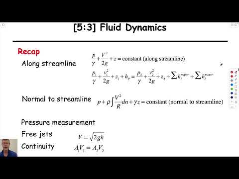
- For flow from a large tank into a free jet, negligible tank velocity and equal atmospheric pressures reduce Bernoulli’s equation to the Torricelli result, V = √(2gH).
- A jet’s horizontal component remains constant during flight, while its vertical component trades kinetic energy for elevation.
- For a finite tank, continuity links upstream and outlet speeds: V₁A₁ = V₂A₂.
- Including the tank’s finite area modifies the outlet-speed result; the large-tank approximation follows as the tank diameter becomes very large.
- A Venturi meter narrows a pipe so fluid speed rises through the throat and static pressure falls relative to the upstream section.
- Pressure taps and a differential-pressure transducer measure P₁ − P₂, the signal used to infer flow.
- A gradual contraction and expansion reduce separation and vortices compared with a sharp orifice plate.
- Excessive constriction can lower pressure toward vapor pressure and cause cavitation, so meter geometry matters.
- Bernoulli’s equation connects pressure and velocity at the upstream section and the throat, while continuity gives V₁A₁ = V₂A₂.
- Combining the equations gives Q = A₂√[2(P₁ − P₂)/(ρ(1 − (A₂/A₁)²))] for ideal horizontal flow.
- The calculation uses the two cross-sectional areas, fluid density, and measured pressure difference to obtain volumetric flow without a moving sensor.
- The area ratio appears squared because the velocities are related through continuity.
- A Pitot tube brings fluid to rest at its forward-facing opening, creating stagnation pressure that can be compared with the surrounding static pressure.
- Bernoulli’s equation converts that pressure difference into flow speed when the measurement points share an elevation.
- A differential manometer relates the pressure difference to fluid-column height: Δp = h(γ_gauge − γ_flow).
- Measuring the pressure difference directly provides better resolution than subtracting two large readings from separate pressure gauges.
- An overshot weir or simple plank across a ditch allows discharge to be estimated from upstream and downstream water depths.
- Bernoulli’s equation along the free surface includes elevation and velocity heads; continuity links velocities through flow areas.
- For a channel of width B, each flow area is depth multiplied by B, so the common width cancels when forming the area ratio.
- When upstream depth is much greater than downstream depth, upstream velocity becomes negligible and the result approaches the free-jet relation.
- Flow over a raised sill behaves like a free jet, with speed controlled by the height of water above the sill.
- Multiplying jet speed by the flow area gives discharge; because area also scales with head, the ideal rectangular-weir relation scales as head to the 3/2 power.
- A dimensionless correction factor can account for geometry and contraction effects such as the vena contracta.
- Notched and rectangular weirs may require different calibration factors even when both use measured water head.
- Bernoulli’s equation expresses total head as elevation head z, pressure head p/γ, and velocity head V²/(2g).
- The energy grade line represents total head; the hydraulic grade line represents elevation plus pressure head.
- In a horizontal, constant-diameter pipe, continuity makes upstream and downstream speeds equal, and ideal Bernoulli flow keeps total head constant.
- The horizontal energy-grade-line result assumes inviscid flow with no energy losses, not a real pipe with friction.
- Continuity requires higher speed in a narrower pipe section, and Bernoulli shows that the increased velocity head comes at the expense of pressure head.
- At a free outlet, pressure is atmospheric, so the energy-grade-line components resolve into elevation and velocity heads.
- In a siphon, raising a constant-diameter tube lowers pressure at its crest; near 30 feet of water lift, pressure can approach water’s vapor pressure and cavitation can occur.
- A pressure drop below atmospheric pressure at the siphon crest explains why trapped air can collect there and disrupt flow.
- A bump on the bottom of an open channel can make the water surface fall rather than rise, consistent with the coupled elevation and velocity requirements of constant total head.
- Bernoulli analysis here assumes steady flow, negligible viscosity, and incompressibility; it is less reliable when compressibility becomes important near Mach 1.
- The steady-flow assumption means conditions do not change from one snapshot to the next.
- Velocity and wind descriptions depend on the reference frame; a cyclist moving into the wind must account for motion relative to the bicycle.
Transcript excerpt
0:01 are transported and distributed in piping systems every single day they can include and chemicals oil and gas or Steam for energy transmission the fluid me yeah so we talk about measuring fluid velocities and flow rates in pipes and in open channels today hence this using beri Swiss mathematician and physicist Daniel beri discovered the direct relationship between the pressure and speed of a fluid flowing in a pip Italian physicist Giovanni Batista vuri also performed experiments on Flow
0:50 and in 1797 he built the first flow meter for closed pipes known as the Venturi tu here is how this measurement method Works differential pressure flow meters have an artificial restriction integrated into the measuring tube Illustrated here by the example of an orifice plate two holes are located in the fight wall one before and one after the orifice plate two separate tubes connect these holes to a differential pressure sensor with its two pressure Chambers separated by diaphragm the tiniest pressure differences in the flowing fluid can be precisely measured if the fluid is not flowing the pressure before
1:39 and after the orifice plate is essentially identical as soon as the fluid starts to flow its velocity around the orifice plate increases significantly because of the Restriction in the cross-section at the same time due to the laws of fluid mechanics the static pressure at this point increases consequently different values are detected in the pressure chambers of the sensor a higher pressure before and a lower pressure after the orus pl this pressure difference is a direct measure for the flow velocity and thus the mass and volume flow in the fight the higher the flow velocity and the resulting drop in pressure around
2:26 the orifice plate the greater the differential pressure me in numerous industrial applications the orifice
This is the start of the transcript. Save this video free for the whole transcript, searchable and time-coded.
In this course
Related notes
Summary, takeaways, and chapters were generated by AI from the video's transcript and may contain errors. The video belongs to its creator, Derek Elsworth.