EECS 373 - Fall 2026 - Lecture 16: "Exam 2 Review"
Overview
The review lays out Exam 2 logistics and revisits the embedded-systems concepts most likely to appear: Cortex-M interrupts, timers, UART, SPI, I²C, ADCs, and DACs. It emphasizes reasoning from timing diagrams and hardware trade-offs, including interrupt priority and stacking, timer capture and PWM, serial framing and bus control, and the speed-versus-resolution choices in converters.
Key takeaways
- Cortex-M exception entry automatically saves R0-R3, R12, LR, PC, and xPSR, while the NVIC handles interrupt selection and prioritization.
- Preemption priority decides whether an IRQ can interrupt another handler, whereas subpriority only orders interrupts at the same preemption level.
- Timer input capture records an external event's counter value for interval measurement, while output compare triggers an event at a programmed count and supports PWM.
- UART has no shared clock, so devices must agree on baud rate and framing; oversampling helps the receiver locate bit centers after detecting a start bit.
- SPI provides controller-generated clocks and chip-select lines, while I²C uses addressed devices and shared open-drain lines with pull-up resistors.
- ADC architectures trade speed against resolution and accuracy: flash is fast, dual-slope is slow and precise, and SAR is a common microcontroller compromise.
Chapters
- Exam 2 is scheduled for Friday from 4:30 to 6:30 in Dow Hall; an assignment-page spreadsheet lists assigned halls.
- The instructor plans to publish homework solutions Wednesday morning and the exam data sheet by Wednesday's lecture.
- Student presentations are 10 to 11 minutes; grading combines a demo presentation, instructor scoring, and peer rankings for clarity.
- The next lecture will cover DMA and printed circuit board design before student presentations begin.
- No notes or phones are allowed; students may bring a graphing calculator, but stored information may be checked.
- The exam includes the existing reference sheet and a new data sheet, with corrections posted to Piazza before a cutoff roughly 12 to 24 hours before the exam.
- Students are encouraged to allocate time across questions and explain a design or code approach to earn partial credit.
- Preparation should focus on homework, labs, and sample exams, including ARM, the ISA, toolchains, ABI, memory-mapped I/O, and lab technologies.
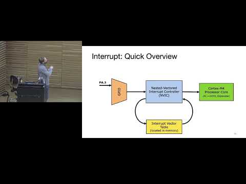
- Peripheral IRQs reach the Nested Vectored Interrupt Controller (NVIC) through dedicated interrupt signals, not as data packets on the bus.
- The NVIC selects and prioritizes pending interrupts, consults the vector table, and directs the Cortex-M core to the relevant handler.
- The vector table begins with the initial stack pointer and reset handler; the first 16 entries are ARM-defined system exceptions, while later entries are device-specific.
- On exception entry, the processor automatically stacks R0-R3, R12, LR, PC, and xPSR so normal execution can resume after the handler.
- An interrupt becomes active when its handler begins; other interrupt requests can remain pending while it runs.
- A higher-preemption-priority interrupt can interrupt a lower-priority handler, creating nested exception state on the stack.
- The special LR value used by BX LR signals exception return, causing the processor to unstack state and restore the interrupted program.
- Pending status preserves requests that arrive during another handler so they can be serviced afterward.
- Preemption priority determines whether one interrupt can interrupt another; subpriority orders interrupts with equal preemption priority.
- Priority grouping divides available priority bits between preemption and subpriority, providing a configurable way to organize interrupt behavior.
- Tail-chaining skips an unnecessary unstack-and-restack sequence when another interrupt is ready at handler exit, saving cycles.
- Late arrival lets a higher-priority IRQ that arrives during exception entry be serviced before the initially selected lower-priority IRQ.
- A timer receives a clock from the clock tree; the XMC4700 timer input can be divided to measure longer intervals.
- The XMC4700 clock divider supports division by powers of two, while the timer counter increments on clock events.
- A counter can reset at its configured period or overflow value, allowing periodic interrupts or control signals.
- Timers may count up, down, or in both directions; bidirectional counting also supports flexible PWM generation.
- Input capture copies the current counter value into a capture register when an external event, such as a GPIO edge, occurs.
- Capture timing can measure intervals between external pulses, such as the rotations of an anemometer, without continuously polling the counter.
- Output compare triggers an event when a timer count matches a programmed comparison value; compare channels are commonly used for PWM.
- Given a timer period and compare value, students should be able to determine the PWM period and duty cycle from a timing diagram.
- UART uses separate TX and RX lines without a shared clock, so the two devices must agree on baud rate and frame settings.
- Connect TX on one device to RX on the other; connecting TX-to-TX and RX-to-RX will not provide the intended communication path.
- The receiver detects a start-bit edge and samples near bit centers using an internal clock commonly 8 to 16 times faster than the baud rate.
- A frame can include 5 to 8 data bits, optional parity, and one or two stop bits; students should decode frames and infer baud rate from timing diagrams.
- SPI uses controller-generated clock and chip-select signals to coordinate communication with a selected peripheral.
- The controller must provide clock pulses even when it only wants to read, because SPI data shifts only as clock edges occur.
- SPI transfers commonly use paired shift registers, exchanging transmit and receive bits at the same time.
- Clock polarity and phase determine idle clock level and which edge samples or shifts data; the peripheral data sheet specifies the required mode.
- I²C uses device addresses instead of a separate chip-select wire for each peripheral, reducing GPIO requirements on multi-device buses.
- Open-drain outputs and pull-up resistors let multiple devices share the lines without directly driving conflicting high and low levels.
- The addressed receiver controls the acknowledgment bit; a missing ACK can indicate an absent device or an incorrect address.
- Pull-up resistance and bus capacitance constrain I²C rise time and maximum speed, so electrical design affects whether timing requirements are met.
- Flash ADCs favor speed but become impractical at high resolution; dual-slope ADCs are slow but can provide high accuracy, as in multimeters.
- Successive-approximation (SAR) ADCs provide a middle ground and are commonly used in microcontrollers.
- For an ADC with N bits and reference range from Vref− to Vref+, the input range is divided into 2^N quantization steps.
- The reference voltages set the measurable range, and practical resolution is limited by quantization error, reference quality, and system noise.
- PWM followed by a low-pass filter is a simple way to produce an analog-like output, including audio signals for a high-impedance piezoelectric disc.
- Resistor-based DACs use weighted values or currents; resistor mismatch can cause output errors, especially when precise binary ratios are required.
- DACs, like ADCs, rely on reference voltages that determine their output range.
- Quantization error is approximately plus or minus half an LSB; noise and component tolerances can make the least significant bit unreliable in practice.
- The instructor distinguishes preemption priority, which governs interruption, from subpriority, which orders requests at the same preemption level.
- The exam is intended to test converter trade-offs, such as fast flash ADCs, accurate but slow dual-slope ADCs, and intermediate-speed SAR ADCs.
- Students should understand quantization error as approximately plus or minus half an LSB while recognizing that real ADC noise can obscure the lowest bit.
- The class is directed to Wednesday's follow-up review of the data sheet and PCB design.
- A student project discussion considers stepper-motor basics and how to explain a motor's operating principle in a 10 to 11 minute presentation.
- For a robot hardware purchase, the instructor recommends presenting high-, medium-, and low-cost options with benefits, risks, shipping uncertainty, and current or torque requirements.
- Project teams should communicate the information needed for a budget decision rather than hiding cost or implementation risks.
- A capture timer records the counter at an external event, much like a stopwatch measuring an interval; a compare timer triggers an event at a programmed count.
- UART oversampling uses a faster internal clock, often 16 times the baud rate, to detect the start bit and locate bit-center sampling times.
- The receiver re-synchronizes at each start bit because sender and receiver clocks can differ slightly.
- The closing discussion returns to an ADC homework problem that maps an analog input voltage into a digital code.
- The conversion uses the reference-voltage range and the number of quantization levels, with rounding to the appropriate code step.
Transcript excerpt
0:00 Okay, today we will provide a review for the second exam. To begin, homework is due today. We will publish the solutions on Wednesday morning for you to review. On Wednesday, or before the lecture, we will publish the data sheet. This exam is similar to the previous one. We will provide you with the data sheet in advance, and we will explain it briefly in the lecture. After that, I will give the final lecture, which will be at least about DMA technology and printed circuit board design. The exam will be on Friday from 4:30 to 6:30 in Dow Hall, the same halls as before. If you are wondering which hall is suitable, you will find a spreadsheet on the assignment page that shows you the halls. The order is alphabetical. If
0:49 your name is not listed in the schedule, choose the hall assigned to you. Okay, today's office hours are from 3:00 to 4:00, right after the lecture. Also, we will begin next week with student presentations. The assignment is available online. This is an opportunity for you to complete some of the ABET requirements. What about the DMA exam? What about Wednesday's exam? No, maybe. I mean, DMA is part of your labs, right? So, there's no harm in asking some questions. We didn't go into much detail about it in the lectures, so I won't ask you very complicated questions, but it's best if you are familiar with DMA. Printed circuit board (PCB) design: You need to
1:36 know what a printed circuit board is. We've talked about that before too. Okay, let's move on to the student presentations. This is part of your ABET requirements, which is to give presentations, as you know, to practice presentation skills. I have already outlined the topics for you. You can search
This is the start of the transcript. Save this video free for the whole transcript, searchable and time-coded.
In this course
Related notes
Summary, takeaways, and chapters were generated by AI from the video's transcript and may contain errors. The video belongs to its creator, Interactive Sensing and Computing Lab.