ME2120 - Dynamics
 Watch on YouTube →
Overview
Ryan C. Cooper uses a two-link gripper with 10 mm and 15 mm dimensions to connect input motion to spring compression, showing that the displacement ratio changes with linkage angle and reaches a 3:2 output-to-input ratio at 45 degrees. He then develops a free-body diagram and quasi-static force analysis, distinguishing external loads from internal hinge forces and showing why force and moment equations alone leave five unknowns for the next class.
Key takeaways
- For the gripper’s 10 mm and 15 mm links, the spring-side displacement follows YB = (l/r) XD tan(theta), so the motion ratio changes as the linkage rotates.
- Near 90 degrees, a small actuator movement produces almost no spring compression; at 45 degrees, a 1 mm input produces 1.5 mm of output movement.
- A free-body diagram must define its system boundary: include external spring or actuator forces, but do not also include the equal-and-opposite internal force at the same connection.
- Quasi-static analysis allows a moving mechanism to be treated with ΣFx = 0 and ΣFy = 0 when changes in momentum are negligible compared with the applied forces.
- Moment equations can eliminate unknown support reactions when taken about their points of application, but the gripper analysis still has five unknowns after only three equilibrium equations.
Chapters
0:00
Stream Check and Return to the Gripper Linkage
- The class checks microphone volume and confirms the stream is online before returning to the gripper problem.
- Cooper frames the question as how much the spring compresses when the gripper actuator moves by 1 mm.
1:30
Why 1 mm of Input Produces Very Little Spring Motion
- Two prior estimates differed sharply: about 1.5 mm of horizontal motion versus roughly 0.07 mm of vertical spring displacement.
- The linkage dimensions are 10 mm and 15 mm, so the same angular rotation produces different arc lengths, including a 1.5 mm displacement on the longer-radius side.
- Near the linkage’s vertical, 90-degree position, a small angular change mostly moves the output horizontally rather than compressing the spring.
7:27
Deriving the Gripper’s Angle-Dependent Motion Ratio
- Cooper compares input displacement XD with spring displacement YB to quantify how actuator movement affects the output.
- The displacement ratio is expressed as XD/YB = (r/l) cot(theta), with r and l representing the linkage dimensions.
- Rearranging gives YB = (l/r) XD tan(theta), so the output-to-input ratio depends on the linkage angle rather than remaining constant.
15:45
At 45 Degrees, the 10 mm and 15 mm Links Give a 3:2 Ratio
- With r = 10 mm and l = 15 mm, the output-to-input ratio becomes 3/2 when theta is 45 degrees.
- At that angle, a 1 mm input displacement produces 1.5 mm of spring-side motion.
- Cooper emphasizes that the kinematic equations describe displacement relationships, not force multiplication; kinetics is needed to find forces.
19:55
Starting the Gripper Free-Body Diagram
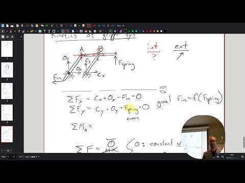
- The analysis shifts from linkage kinematics to kinetics, beginning with the actuator input force and the spring force.
- The diagram represents only half of the symmetric gripper, with the other half treated as a mirror image.
- The spring and actuator forces alone do not account for the supports and constraints that keep the linkage from moving freely.
27:33
Separate External Loads from Internal Hinge Forces
- A free-body diagram must include forces external to the chosen system, including the actuator force, spring force, and support reactions.
- If the spring force is drawn as an external load, its equal-and-opposite reaction should not also be included on the same system diagram.
- Forces between connected bars at hinges A and B are internal to the combined linkage and cancel in equal-and-opposite pairs.
31:33
Use the Quasi-Static Assumption to Set Force Sums to Zero
- Newton’s second law gives the force balance as ΣF = ma, but the class seeks a simpler analysis without acceleration terms.
- Under a quasi-static assumption, the linkage can move while changes in linear or angular momentum are treated as negligible.
- This approximation allows the analysis to use equilibrium-style equations, ΣFx = 0 and ΣFy = 0.
37:57
Count Unknowns Before Solving for Actuator Force
- The target is the relationship between the spring force and the actuator input force, such as the input needed to oppose a 50 N spring load.
- The horizontal and vertical force balances are not enough by themselves because several reaction-force components remain unknown.
- Taking moments about a carefully selected point provides an additional independent equation.
41:17
Choose a Moment Center and Apply the Right-Hand Rule
- Points O and C are both possible moment centers; choosing one can eliminate reaction forces whose lines of action pass through that point.
- For a moment about C, the CX force has zero moment arm, while CY has a moment arm identified as 5 in the diagram.
- Cooper uses the right-hand rule to assign positive and negative moment directions and illustrates it with the direction of a screw.
46:47
Force Analysis Ends with Five Unknowns and Three Equations
- The moment balance assigns a negative moment contribution to the input force and a positive contribution to the spring force under the chosen sign convention.
- Combining the two force equations with one moment equation yields three equations for five unknowns.
- The input-to-spring force relationship therefore remains unsolved; Cooper leaves the additional constraint or reduction step for the next class.
Summary, takeaways, and chapters were generated by AI from the video's transcript and may contain errors. The video belongs to its creator, Professor Ryan C. Cooper.