ME2120 - Applied Mechanics II
 Watch on YouTube →
Overview
Ryan C. Cooper develops the kinematics of a symmetric linkage by distinguishing moving rigid parts from pins and forces, then describing hinge positions with vectors and a single changing angle. He derives relative-position and loop-closure relationships, connects hinge height to spring compression, and begins a 90-degree, 1-millimeter input-displacement exercise that remains open for the next class.
Key takeaways
- In planar mechanism kinematics, a free rigid bar needs three coordinates, x, y, and orientation, but linkage constraints can reduce the system to one independent angle.
- For the illustrated bar, point A is located by x_A = L cos θ and y_A = L sin θ; fixed lengths and constraints determine the other hinge positions from θ.
- Relative-position vectors simplify hinge calculations: with A-to-B separation D along x, R_B = R_A + D i.
- The spring is treated as a force element, not a flexible rigid-body part, and its compression can be tracked through the relevant hinge's y-coordinate.
- A linkage loop must close: the successive position vectors from ground through the connected bars sum to the fixed ground-to-ground vector.
- A 1-millimeter actuator or slot displacement does not imply a 1-millimeter gripper displacement; the output depends on linkage geometry and configuration.
Chapters
0:00
Kinematics Before Forces in Mechanism Analysis
- Ryan C. Cooper frames the lesson around mechanism kinematics, meaning the geometry and description of motion.
- He distinguishes position and motion relationships from forces and acceleration, which belong to later kinetics analysis.
- Vectors and trigonometry provide the tools for describing the moving linkage.
2:05
Counting Linkage Parts, Pins, and Spring Forces
- The example contains three moving rigid parts plus fixed ground, with O and C acting as stationary anchors.
- Pins move with the connected parts but are treated as constraint points, not independent rigid bodies.
- A pin constraint implies forces between parts in a later kinetics analysis, even though the pin is not a separate moving part here.
- The spring is modeled as a force, such as a force proportional to displacement by stiffness K, rather than as a flexible moving body.
10:00
Describing Part One with an Angle and Cartesian Coordinates
- Cooper places an origin at O and notes that a mechanism can use as many coordinate systems as its analysis requires.
- A freely moving rigid bar in a plane needs x-position, y-position, and orientation; linkage constraints reduce the independent coordinates.
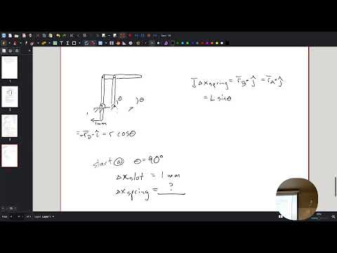
- For a bar of length L at angle θ, point A has coordinates x_A = L cos θ and y_A = L sin θ.
- The constrained linkage can be described with one changing angle because its other positions follow from fixed lengths and geometric constraints.
18:26
Finding Hinge B from the Linkage Geometry
- The class identifies a geometric relationship between hinges A and B: their y-components are equal in the simplified parallelogram arrangement.
- Cooper presents the equality of projected components as an equivalent dot-product relationship.
- The horizontal separation between the hinges is the fixed distance D, which simplifies the otherwise nonlinear linkage geometry.
27:12
Using Relative Position to Locate Hinge B
- Cooper defines the vector from A to B as a relative-position vector, R_B/A.
- Because the separation is fixed along the x-axis, R_B/A = D i + 0 j.
- Adding vectors gives R_B = R_B/A + R_A, or x_B = D + L cos θ and y_B = L sin θ.
- This vector approach avoids separately solving several trigonometric relationships for the same hinge location.
30:17
Relating Hinge Height to Spring Compression
- The y-coordinate of B tracks the spring's displacement in the illustrated mechanism.
- As the hinge height approaches zero, the spring becomes more compressed.
- The linkage's symmetry lets the analysis focus on one side rather than treating every moving part independently.
- Cooper describes the motion as constrained by circular paths while emphasizing that the spring itself is represented through its force.
33:14
Locating Ground Hinge C and Closing the Vector Loop
- Hinge C is mounted to ground, so its position is fixed and has no y-component in the chosen coordinate system.
- The vector path from the origin through A and B to C must sum to the fixed ground separation D i.
- The loop-closure relation is R_A + R_B/A + R_C/B = D i.
- This relationship becomes useful for a general four-bar linkage when bar lengths and angles are not kept parallel by symmetry.
39:10
Reducing the Linkage Configuration to One Variable
- The position equations show that knowing θ determines the locations of the hinges and the spring displacement.
- Cooper connects general vector components to the practical quantities of interest, including hinge position and spring compression.
- Fixed dimensions such as L and D are constants; θ is the key changing configuration variable in this example.
42:06
Setting Up a 90-Degree, 1-Millimeter Input Exercise
- The class considers starting the mechanism at θ = 90 degrees and moving the lower slot by 1 millimeter.
- The task is to determine how far the gripper closes, using the kinematic relationships developed earlier.
- Cooper asks students to identify any missing information as well as attempt the displacement calculation.
- At 90 degrees, the chosen coordinate definition gives an initial x-position of zero, which students initially confuse with zero change in x.
49:13
Separating Initial Position from Displacement
- Cooper clarifies that a starting x-coordinate of zero does not mean the point's change in x is zero.
- Moving the slot left by 1 millimeter makes point A move right, but the gripper motion is not necessarily 1 millimeter.
- The input-output relationship depends on the linkage dimensions and the current angle, so the displacement ratio is not directly one-to-one.
- The numerical gripper displacement is left unresolved for the next class.
51:28
Following Up on the Linkage Displacement Method
- After the scheduled class ends, a brief discussion revisits how end-point motion relates to the rotating arms.
- The suggested process is to use the known displacement to determine the next angle, then calculate the corresponding position.
- The exchange refers to circular motion and changing geometry, but does not establish a final numerical result for the 1-millimeter exercise.
55:00
Office Hours and Choosing an Engineering Solution Approach
- Cooper directs a student named Thomas to the Calendly link for arranging office hours and encourages attending and making an effort.
- The discussion turns to whether engineering case studies have one required answer or allow multiple valid approaches.
- A student mentions prior work involving friction, acceleration, and energy; the exchange emphasizes the reasoning process rather than a single method.
- The transcript ends during this informal discussion, without a complete worked solution to the linkage exercise.
Summary, takeaways, and chapters were generated by AI from the video's transcript and may contain errors. The video belongs to its creator, Professor Ryan C. Cooper.