ece1756_lecture7_2026_fpga_arch_types_and_low_level_circuitry
Overview
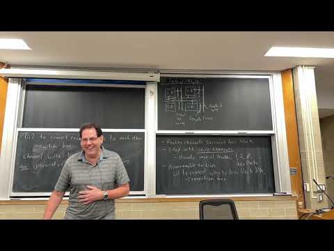
Vaughn Betz compares hierarchical and island-style FPGA routing, showing how Rent’s rule explains why island-style channel width can remain nearly constant for circuits with good locality and grow only as capacity to the 0.25 power for designs with Rent exponent 0.75. He explains why modern FPGAs combine small hierarchical logic clusters with island-style routing, then begins a transistor-level area estimate: a 4-input LUT built with pass-transistor multiplexers is estimated at 217 minimum-width transistor area units.
Key takeaways
- For an M-by-M island-style FPGA, Rent’s rule gives a channel-width requirement proportional to M^(2p−1): p ≤ 0.5 permits constant width, while p = 0.75 requires width proportional to M^0.5.
- Island-style routing is fast for nearby blocks and scalable with good placement, but long-distance performance depends on mixing longer wire segments with short ones.
- Modern FPGA logic commonly uses a hybrid structure: groups of 4 to 32 LUT-and-register BLEs form local logic clusters, which connect through island-style routing.
- Timing-driven routing is essential because island-style architectures offer many possible paths; critical nets need direct routes and fast wires, while poor CAD choices can erase the architecture’s advantages.
- FPGA startup teams need to develop CAD tools alongside hardware because placement and routing determine whether the architecture can be programmed effectively.
- A transistor-level 4-input LUT estimate reaches 217 minimum-width area units when pass transistors are sized for five times minimum drive, illustrating why LUT and routing circuitry both matter in FPGA area estimates.
Chapters
- Hierarchical FPGAs exploit circuit locality and use Rent’s exponent to determine how much wiring higher levels need.
- Their drawbacks are slow, long top-level wires and routing detours between physically nearby blocks placed in different hierarchy branches.
- Island-style FPGAs place logic, RAM, and DSP blocks among prefabricated routing channels.
- Routing channels contain prefabricated wire segments, with modern architectures mixing lengths such as 1, 2, and 4 logic blocks.
- Connection boxes link logic-block inputs and outputs to routing wires; switch boxes connect routing wires to one another.
- Channel width, W, is the number of wires in each routing channel.
- Short wires let physically close blocks communicate quickly, matching the locality expected when a circuit has a low Rent exponent.
- A route across 60 blocks using only length-2 segments may require about 30 segments in each direction, adding many programmable switches.
- Longer segments, such as length-10 wires, reduce switch count for distant connections, though no architecture makes across-chip communication fast.
- An M-by-M array contains M² logic blocks and has 4M routing channels around its perimeter.
- With W wires per channel, the array supplies 4MW wires at its boundary.
- The architecture goal is to increase logic capacity without letting routing consume a steadily larger fraction of chip area.
- Rent’s rule models circuit wiring demand as a constant times the amount of logic raised to the Rent exponent p.
- For an M-by-M array, the wiring demand is proportional to M^(2p), while the boundary supply is 4MW.
- Requiring demand to stay within supply gives a channel-width requirement proportional to M^(2p-1).
- For Rent exponent p ≤ 0.5, the exponent 2p−1 is nonpositive, so channel width need not increase as the array grows.
- This supports replicating the same physical FPGA tile without widening routing channels or redesigning the layout.
- Pipelines, SRAM structures, and regular systolic arrays can have strong locality and roughly square-root growth in external connections.
- For p = 0.75, the channel width must grow proportional to M^0.5.
- Since logic capacity is M², this is equivalent to channel width growing as the number of logic blocks to the 0.25 power.
- A 16-fold increase in array dimension requires only a twofold channel-width increase for this less-local design case.
- Real designs rarely consist entirely of high-Rent control logic, so placement tools can spread less-local portions across the chip.
- Poor placement can push effective Rent exponent toward 1, making routing demand and congestion disastrous.
- Channel width grows across real FPGA families, but good placement keeps that growth relatively slow.
- Island-style routing offers many route choices, including different wire lengths, directions, and path orders.
- Timing-driven routers repeatedly analyze path delays and prioritize fast, direct routes for critical connections.
- Routing flexibility can improve results, but weak CAD tools may choose slow detours or waste short wires on timing-critical paths.
- Vaughn Betz describes how Altera initially judged island-style routing poorly because its router did not exploit the architecture effectively.
- Betz’s team improved CAD algorithms and demonstrated that the additional routing choices could produce better results.
- Architecture comparisons require CAD flows that optimize each candidate fairly, or tool limitations can produce misleading conclusions.
- Betz identifies inadequate CAD tools as a common cause of FPGA startup failure: users cannot effectively program hardware without them.
- Placement and routing tools are difficult to develop and can be harder than the hardware itself.
- Developing CAD and architecture together makes it possible to test whether routing structures are usable before committing to a chip.
- The common hybrid uses hierarchy for small local groups and island-style routing to connect those groups across a large chip.
- Hierarchical wiring is effective at small scales, where its wires remain short; its fixed bandwidth and long wires become problematic at large scales.
- This avoids making the entire FPGA hierarchical while preserving useful local structure.
- A basic logic element, or BLE, commonly combines a lookup table with a flip-flop.
- Several BLEs and their local routing form a logic cluster, which becomes a function block connected to island-style routing.
- Altera Agilex 7 groups LUT and register resources into ALMs, then groups ALMs into LABs before island-style routing.
- A typical cluster contains roughly 4 to 32 BLEs and uses local routing to connect their logic.
- Clustering groups related BLEs, reducing the global placement problem by a factor comparable to the cluster size.
- Smaller placement problems can shorten compile time, and connections contained within a cluster can also ease routing.
- Registers within a cluster often share a clock because related logic commonly belongs to the same clock domain.
- Cluster-level sharing can also reduce routing for clock enables, synchronous clears, and asynchronous clears.
- Sharing selected control signals saves programmable muxing and wiring without forcing unrelated data inputs to be identical.
- FPGA function blocks include RAM and DSP resources as well as logic clusters.
- A six-input LUT stores 64 SRAM bits, while a prominent Agilex 7 RAM block holds about 20 kilobits; an 18-by-18 multiplier is also larger than a LUT.
- Grouping LUTs into clusters makes logic blocks more comparable in size to RAM and DSP blocks, simplifying replicated routing-channel design.
- FPGA architecture studies need estimates of both logic area and programmable-routing area.
- Betz begins with a simplified island-style design using one 4-input LUT per logic block, length-1 wires, and mux-based programmable switches.
- Transistor area is usually dominant because LUTs and programmable switches contain many transistors, but metal fit should also be checked.
- Counting only routing switches omits LUT cost and can make unrealistic designs with enormous LUTs appear nearly free.
- Counting transistors includes both LUTs and routing muxes, but treats small internal devices and large output drivers as equivalent.
- Layout-area estimates account for transistor sizing and wiring constraints; full layout is most useful after architecture candidates have been narrowed.
- The minimum-width transistor model uses the repeatable area of a smallest useful transistor, including contact and spacing requirements.
- Larger drive strength can come from widening a transistor or placing multiple transistors in parallel; FinFETs use additional fins for similar effect.
- The model estimates relative area as 0.5 + 0.5 times drive strength, so a transistor at twice minimum drive takes about 1.5 area units.
- A K-input LUT stores 2^K truth-table bits in SRAM cells and selects one value through a mux tree.
- The two-input example uses four 6-transistor SRAM cells and NMOS pass transistors controlled by the two inputs.
- The pass-transistor tree reduces the candidate truth-table values stage by stage until the selected value reaches the output.
- NMOS pass transistors pass zero strongly but pass a one only to about VDD−VT, so the output needs an inverter and weak keeper to restore the level and prevent excess current.
- A 2-input LUT example totals 37 transistors: 24 for four SRAM cells, 6 pass transistors, 6 inverter transistors, and 1 keeper.
- For a K-input LUT, the pass-transistor count is 2^(K+1)−2; with pass devices sized to five times minimum drive, the 4-LUT estimate is 217 minimum-width transistor area units.
Transcript excerpt
0:00 So, now for your probably your last lecture before reading week, right? Or last half lecture before reading week. Unless you have one really late tonight. I don't think anybody has a lecture after this. Is that right? Yes, you're like an hour and a half away from reading week. So, we try to make maximum use of it. Okay, so at the end of last lecture, we were talking about um one of the styles of FPGAs called hierarchical. Uh where we we leverage the fact that circuits, like designs, have a hierarchy and we build an FPGA that also has a hierarchy. And we benefited from the fact that most connections are kind of near neighboring logic or modules. So, we didn't need as many wires at the kind of the top level of the hierarchy uh as we did at the bottom level of the hierarchy.
0:47 Uh and that was helpful. That helped us scale to, you know, bigger devices without you know, too much wiring overhead. We couldn't scale linearly. We had to add more wiring as we went to bigger devices. Um but we didn't have to add it at too high a rate rate. And how fast we had to add how much interconnects we had to add at the upper levels of the hierarchy was a a function of this thing called the rent parameter, right? The rent exponent. So, how how much locality do we think we have? Um Locality is this property where you tend to talk to things near you in a circuit versus things far away. Uh so, depending on how much locality we thought a the typical design would have, we could use we thought we had a pretty good locality, like a low rent exponent, we could use not too much wiring in the
This is the start of the transcript. Save this video free for the whole transcript, searchable and time-coded.
In this course
Related notes
Summary, takeaways, and chapters were generated by AI from the video's transcript and may contain errors. The video belongs to its creator, Vaughn Betz.