NDSU ECE 211 Lecture 17
 Watch on YouTube →
Overview
Roger Green concludes the NDSU ECE 211 op-amp unit by explaining open-loop comparators and how positive feedback turns a comparator into a Schmitt trigger. He derives the upper and lower switching thresholds from the R1–R2 voltage divider, shows the resulting hysteresis loop, and connects it to noise-resistant switching such as a home thermostat with 68°F and 72°F setpoints.
Key takeaways
- An open-loop op amp makes an effective comparator because a tiny differential input can drive its output to V+ or V−.
- Swapping which comparator input receives VN versus VREF reverses the relationship between input level and output rail.
- In the positive-feedback circuit, VX = [R1/(R1 + R2)]Vout, so the switching threshold depends on whether the output is at V+ or V−.
- A Schmitt trigger has separate upper and lower thresholds; the output switches at one threshold while the input rises and the other while it falls.
- Hysteresis reduces noise-induced switching by requiring the input to cross a threshold gap rather than fluctuate around one point.
- A thermostat using 68°F to turn heat on and 72°F to turn it off illustrates how hysteresis prevents rapid heater cycling.
Chapters
0:00
Op-Amp Review and the Open-Loop Comparator
- The lecture wraps up op-amp applications after reviewing practical limits such as common-mode rejection, saturation, slew rate, and input offset.
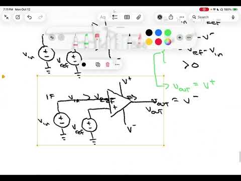
- A comparator uses an op amp without a negative-feedback path, unlike closed-loop amplifiers designed for controlled gain.
- Because open-loop gain is enormous, even a small difference between the input terminals can drive the output to a supply rail.
5:00
Comparator Output Polarity and Reference Thresholds
- With VN on the inverting input and VREF on the non-inverting input, VN < VREF produces a positive differential voltage and drives the output to V+.
- When VN > VREF in that configuration, the output saturates at V−; the rail output acts as a binary decision signal.
- Swapping VN and VREF between the op-amp inputs reverses the logic, so an input above the reference can instead produce V+.
11:00
Adding Positive Feedback Through R1 and R2
- The circuit feeds Vout back to the non-inverting input through R2, with R1 connecting that input node to ground.
- Assuming ideal op-amp input current, the non-inverting voltage follows the divider: VX = [R1/(R1 + R2)]Vout.
- The input VN connects to the inverting terminal, so the output remains railed and its feedback-dependent threshold changes with the output state.
14:00
Deriving the Schmitt Trigger’s Upper and Lower Thresholds
- When Vout = V+, the switching threshold is VT,upper = [R1/(R1 + R2)]V+; crossing it switches the output to V−.
- When Vout = V−, the threshold is VT,lower = [R1/(R1 + R2)]V−; falling below it switches the output back to V+.
- With positive and negative supply rails, these thresholds lie on opposite sides of zero, and their separation depends on the resistor ratio and rail voltages.
19:30
Hysteresis Loop: State Depends on Input Direction
- On an input-output plot, increasing VN holds the output at V+ until the upper threshold, where it jumps to V−.
- After the output switches low, further increases do not switch it back; VN must decrease past the lower threshold to restore V+.
- The gap between the two thresholds forms a hysteresis loop, unlike a basic comparator that switches at one VREF.
26:00
Schmitt Trigger Noise Immunity and Thermostat Example
- A comparator with positive feedback and hysteresis is called a Schmitt trigger; the threshold gap reduces sensitivity to small input noise.
- A thermostat can turn heating on below 68°F and off above 72°F, avoiding rapid on-off cycling near a single temperature threshold.
- The lecture closes the op-amp chapter and previews capacitors as the next topic.
Summary, takeaways, and chapters were generated by AI from the video's transcript and may contain errors. The video belongs to its creator, Roger Green.