MIME 4450 Lec 5 9 15 26
 Watch on YouTube →
Overview
A MIME 4450 lecture explains how electromechanical relays implement Boolean AND, OR, NOT, and start-stop memory circuits, then connects relay ladder diagrams to PLC programming. It covers normally open and normally closed contacts, pneumatic timers, fail-safe switch selection, relay limitations, and the automotive changeover demands that helped drive PLC adoption, including early Modicon systems.
Key takeaways
- A normally open relay contact represents a Boolean variable, while a normally closed contact represents its negation, making relay ladder diagrams a physical form of Boolean logic.
- A start-stop memory circuit uses a feedback contact to hold its state; parallel start buttons and parallel stop buttons allow control from multiple locations.
- Physical relay contacts and pneumatic timers can be replaced by PLC logic, reducing wiring and making changes easier, though legacy equipment may remain in use because existing processes are difficult to modify.
- Normally open versus normally closed switch selection is a safety decision: engineers must consider how a process responds to faults such as a broken wire.
- PLC adoption in automotive plants was driven in part by yearly model changes that made relay-panel rewiring costly and time-consuming; early Modicon controllers let manufacturers make changes through programming instead.
- Relay contacts have finite mechanical life, around one million operations as discussed in the lecture, while PLC logic avoids implementing each AND/OR function with separate external relay wiring.
Chapters
0:00
Relay Demonstration: AND Logic and Start-Stop Memory
- Two relays are wired as an AND circuit: either push button alone leaves the output off, while pressing both turns it on.
- A relay start-stop circuit retains its state after the start action, then switches off when the stop button is pressed.
- Relays can implement both Boolean logic and memory without a computer.
4:30
Relay Contacts, Ladder Rungs, and Telegraph Origins
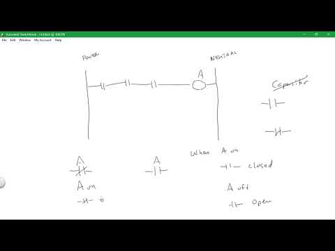
- A ladder circuit is read from power on the left toward neutral on the right, with contacts controlling a relay coil.
- A normally open contact represents a relay's state; a normally closed contact represents its inverse, or NOT.
- Relays were developed to regenerate telegraph signals over long distances, replacing human operators who retransmitted messages at intervals of roughly 20 miles.
- Railroad crossing gates illustrate an early relay memory application: a train activates a start condition and later resets it.
13:10
Switch Limits, Pneumatic Timers, and Boolean Ladder Logic
- Adding many physical contacts to one push button becomes difficult because each contact adds spring resistance; relays can multiply the available control contacts.
- Pneumatic timers create delays by metering air through a dashpot, but a timer head may be either on-delay or off-delay and require rewiring to change behavior.
- A programmable controller can replace multiple physical logic elements and timers, with inputs and outputs wired externally and logic handled in software.
- Ladder diagrams express AND, OR, NOR, exclusive OR, and NOT; contact terminology also varies, with normally open/closed commonly called make/break in Europe.
19:15
Truth Tables and Relay-Based AND/OR Circuits
- A two-input AND circuit turns on only for input state 1,1; states 0,0, 0,1, and 1,0 leave its output off.
- Changing a contact arrangement can make either input activate the output, producing an OR circuit.
- Elementary diagrams and truth tables connect physical relay wiring to Boolean variables and PLC ladder logic.
21:30
Memory Circuits, Multiple Stations, and De Morgan's Law
- A relay memory circuit combines a start path, a feedback path that holds the state, and a stop path that resets it.
- Multiple start buttons can be wired in parallel, as can multiple stop buttons, allowing a fan to be controlled from locations such as a first floor and a roof.
- Normally closed stop inputs implement a negated function; De Morgan's law converts the negated OR of stop actions into an AND of their complements.
26:00
Level Switches, Fail-Safe Contacts, and Process Safety
- A level switch can use a float-like mechanism, similar to the ball in a toilet tank, and may provide normally open and normally closed contacts.
- Contact choice depends on the process and the consequences of a fault, such as whether a disconnected wire could cause a tank or control room to flood.
- Control engineers must evaluate failure states and select contacts accordingly; the lecture describes testing inputs and outputs in both high and low states for some European equipment approvals.
32:10
Quiz Guidance and the Tradeoffs of Physical Relays
- The upcoming 20-minute quiz covers a robotics text and three Boolean-logic chapters; students may bring 5 to 10 pages of notes, but not books or computers.
- Relays are quick to assemble for simple circuits, but their contacts wear out after roughly one million or more operations.
- A PLC keeps AND/OR logic inside the controller program, reducing external wiring to inputs and outputs while preserving ladder diagrams as a familiar representation.
36:10
Automotive Changeovers, Modicon PLCs, and Relay Terminals
- Annual automotive model changes once required extensive control-panel rewiring, sometimes keeping controls engineers working day and night for a month or six weeks.
- A specification from the automotive industry led to early PLC adoption by GM, Chrysler, and Ford; early Modicon systems replaced much of the panel rewiring with program changes.
- The lecture identifies a relay coil at terminals 13 and 14, and a changeover contact with terminal 9 common, terminal 5 normally open, and terminal 1 normally closed.
- Elementary drawings show left-to-right relay logic, where normally open contacts represent a variable and normally closed contacts represent its inverse.
Summary, takeaways, and chapters were generated by AI from the video's transcript and may contain errors. The video belongs to its creator, Wm_T Evans.