ME2120 - Dynamics
 Watch on YouTube →
Overview
Professor Ryan C. Cooper uses a spring-loaded gripper linkage to connect spring force to the actuator force needed to hold or move the mechanism. He reviews a nine-equation, nine-unknown force-and-moment system, calculates spring length from linkage geometry using a 45 mm free length and a 30 N/m spring rate, and identifies the loss of mechanical advantage as the linkage approaches zero angle.
Key takeaways
- The three-part linkage model produces nine force-and-moment equations for nine unknowns, allowing actuator force to be related to spring force.
- The spring’s changing length follows the geometry H + 2L sin θ, with H = 20 mm and L = 15 mm in the worked example.
- With a 45 mm free length, the spring is 50 mm long at the initial position, giving 5 mm of extension before the linkage closes and compresses it.
- Hooke’s law converts the calculated length change into spring force; the stated spring rate is 30 N/m, or 30 mN/mm.
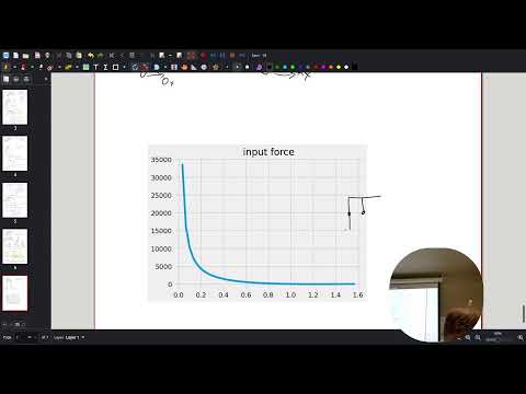
- The input-force relationship includes L/(R tan θ), so the required actuator force increases as θ approaches zero and mechanical advantage deteriorates.
Chapters
0:00
Relating Spring Force to the Gripper’s Required Input Force
- Cooper revisits a linkage problem from the previous class and asks how the spring force relates to the force applied by the actuator.
- The proposed relationship depends on linkage lengths, including L and R, and the angle θ.
- The goal is to use the previously solved kinematics to determine spring force at each position.
3:00
Students Work Backward from the Force Relationship
- Students use their notes and the prior equations to derive the relationship between spring force and input force.
- Cooper gives the class time to compare approaches and check the algebra before reviewing the result.
- The central task is reducing the force equations to a single input-force expression.
8:30
Reviewing the Nine Force and Moment Equations
- The linkage analysis contains nine equations: force balances in x and y and a moment equation for each of three parts.
- The system has nine unknowns, and the desired output is the actuator force expressed in terms of spring force.
- Cooper checks a moment arm and questions whether the correct distance is R or D, emphasizing the need to verify geometry.
12:00
Checking the Moment Arm Against the Linkage Geometry
- Cooper returns to the original diagram, where the applied force acts at a distance R from the pivot.
- The moment contribution depends on the perpendicular component of the position vector, involving a sine of θ.
- The class distinguishes the link-to-link spacing D from the radius R used for the force’s moment arm.
15:30
Reducing the Linkage Equations During Group Work
- Students continue simplifying the force and moment balances to isolate the actuator-force relationship.
- The derivation must account for reaction forces as well as the spring force acting through the connected links.
- The extended work period underscores why checking signs, distances, and each algebraic step matters in a multi-body system.
31:30
Tracking Gripper Motion as the Link Angle Changes
- Cooper shifts from force balance to the kinematics that determine the spring’s changing length.
- The linkage motion changes the gripper position as θ moves from 90° toward 0°.
- The class discusses roughly 15 mm of motion on each side and compares that travel with the slot mechanism’s displacement.
35:00
Finding the Spring Length from Link Coordinates
- The vertical coordinate of a link point is written as L sin θ, while the horizontal coordinate involves R cos θ.
- The spring length is modeled as the fixed height H plus the vertical contributions from two links: H + 2L sin θ.
- The stated dimensions include L = 15 mm and H = 20 mm.
39:00
Applying Hooke’s Law to the 45 mm Spring
- Spring deformation is calculated as current length minus the 45 mm free length.
- Cooper uses a spring rate of 30 N/m, equivalent to 30 mN/mm when working in millimeters.
- At the initial 90° position, H + 2L gives a 50 mm spring length, or 5 mm of extension; as the linkage closes, the spring transitions into compression.
44:00
Using Spring Force to Determine Actuator Force
- Once spring force is known as a function of θ, it can be substituted into the linkage force relationship to find the required input force.
- The derived relationship is discussed in the form F_input = F_spring L/(R tan θ).
- The result connects the spring’s changing force to the actuator force needed to keep the gripper from moving.
47:30
Mechanical Advantage Falls Near Zero Linkage Angle
- As θ approaches 0°, tan θ becomes small, so the required input force rises sharply for a given spring force.
- Cooper identifies the worsening force ratio as a loss of mechanical advantage near the gripper’s closed position.
- The class discusses plugging in numerical values and using a graph to communicate how the input force changes across the motion.
Summary, takeaways, and chapters were generated by AI from the video's transcript and may contain errors. The video belongs to its creator, Professor Ryan C. Cooper.