Lecture 10 14
 Watch on YouTube →
Overview
The lesson develops Denavit–Hartenberg (DH) forward kinematics by assigning frames, finding θ, α, R, and D, and multiplying adjacent homogeneous transforms. It works through a three-joint SCARA robot and a three-prismatic-joint Cartesian robot, emphasizing how joint variables enter the DH table and how DH results can be checked against rotation-matrix solutions.
Key takeaways
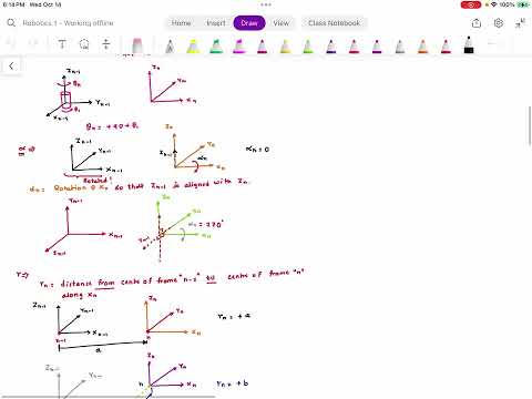
- Standard DH parameters encode each frame transition with θ, α, R, and D: θ rotates about Zₙ₋₁, α rotates about Xₙ, R translates along Xₙ, and D translates along Zₙ₋₁.
- Joint variables enter the DH table according to joint type: revolute motion changes θ, while prismatic motion changes D.
- Standard DH cannot represent a translation offset along Y; rotation matrices remain applicable, while modified DH can introduce extra frames to handle more complex geometry.
- For the SCARA example, the table is (θ₁, 0, A₂, A₁), (θ₂, 180°, A₃, A₅), and (0, 0, 0, A₄ plus the prismatic displacement).
- For the Cartesian example, all R values are zero, the θ values are 90°, 90°, and 0°, the α values are 90°, 270°, and 0°, and each D combines a fixed offset with prismatic travel.
- The end-effector transform is found by multiplying adjacent transforms in order; comparing this product with a rotation-matrix solution provides a practical verification of the DH setup.
Chapters
0:00
DH Workflow: Frames, Parameters, and Forward Kinematics
- Begin with a kinematic diagram that represents links as line segments and joints as simplified shapes such as cylinders or cubes.
- Assign frame 0 and one frame at each joint; orient each Z axis through its joint axis and use a right-handed coordinate system.
- The DH task is to identify four parameters per frame transition: angular θ and α, and distances R and D.
3:03
Build the DH Table and Compose Homogeneous Transforms
- A robot with four frames has three DH rows, one for each transition between adjacent frames.
- The standard homogeneous transform is supplied in terms of θ, α, R, and D; substitute the table values to form each adjacent-frame transform.
- For frames 0, 1, and 2, compute ⁰H₁ and ¹H₂, then multiply them to obtain ⁰H₂; MATLAB or manual matrix multiplication can be used.
6:07
Determine θ and α from Adjacent Frame Axes
- θₙ is measured about Zₙ₋₁ so Xₙ₋₁ aligns with Xₙ; include a revolute joint angle in θ.
- αₙ is measured about Xₙ so Zₙ₋₁ aligns with Zₙ, making the rotated vector belong to the previous frame.
- The two rotations use different axes and frame relationships, which makes α especially easy to misidentify.
10:00
Interpret R and D, and Recognize the DH Offset Limitation
- R measures the displacement between frame origins along the new Xₙ axis; D measures displacement along the previous Zₙ₋₁ axis.
- A revolute joint variable contributes to θ, while a prismatic joint variable contributes to D.
- Standard DH parameters have no translation term for a Y-direction offset; use rotation matrices for such cases or consider modified DH with extra frames.
12:10
Three-DOF Exercises: Compare DH and Rotation-Matrix Results
- The lesson shifts from earlier two-DOF examples to three-degree-of-freedom robots.
- The planned in-class exercise asks students to solve forward kinematics with both rotation matrices and DH parameters.
- The two methods should produce the same homogeneous transformation.
15:13
Set Up the SCARA Robot Frames and Link Geometry
- The first worked example is a SCARA robot with two revolute joints followed by one prismatic joint.
- Four frames—0 through 3—produce three DH rows; each joint axis defines its frame’s Z direction.
- The diagram labels link and offset distances A₁ through A₅, joint angles θ₁ and θ₂, and the prismatic displacement D₃.
20:53
Prepare the SCARA DH Table
- Create three rows, each containing θ, α, R, and D for transitions 0→1, 1→2, and 2→3.
- Before filling in the table, identify each θ by rotating about the preceding frame’s Z axis until the X axes align.
- Students are asked to show intermediate steps rather than jump directly to parameter values.
29:04
Find the SCARA Joint-Axis Rotations θ₁, θ₂, and θ₃
- For the first transition, X₀ and X₁ already align, so θ₁ is the revolute joint angle.
- For the second transition, X₁ and X₂ align, so θ₂ is its revolute joint angle.
- For the third transition, X₂ and X₃ align and the joint is prismatic, so θ₃ is zero.
33:49
Find SCARA Twist Angles α₁, α₂, and α₃
- α₁ is zero because Z₀ and Z₁ already align when the previous Z axis is considered in the new frame.
- For α₂, rotate Z₁ about X₂ in the positive direction until it aligns with Z₂; the required angle is 180°.
- For α₃, Z₂ and Z₃ align, giving α₃ = 0°; revolute joint angles do not belong in α.
44:22
Measure SCARA Link Offsets R Along Each New X Axis
- R is measured from one frame origin to the next along Xₙ, so its sign depends on the positive direction of that axis.
- The worked diagram gives R₁ = A₂ and R₂ = A₃.
- There is no displacement along X₃ between frames 2 and 3, so R₃ = 0.
51:09
Add the SCARA Prismatic Displacement to D₃
- D is measured along Zₙ₋₁, and the SCARA prismatic joint’s translation is included in D₃.
- The resulting distances are D₁ = A₁, D₂ = A₅, and D₃ = A₄ + D₃, where the repeated D₃ denotes the joint displacement.
- The completed parameter rows are (θ₁, 0, A₂, A₁), (θ₂, 180°, A₃, A₅), and (0, 0, 0, A₄ + D₃).
56:23
Substitute SCARA Row 1 into the Homogeneous Transform
- For ⁰H₁, substitute θ₁, α₁ = 0, R₁ = A₂, and D₁ = A₁ into the standard DH transform.
- Using cos(0) = 1 and sin(0) = 0 simplifies the rotation terms.
- This produces the first transform needed for the complete SCARA forward-kinematics chain.
59:43
Substitute SCARA Row 2 with α₂ = 180°
- For ¹H₂, use θ₂, α₂ = 180°, R₂ = A₃, and D₂ = A₅.
- The substitutions cos(180°) = −1 and sin(180°) = 0 determine the signs and zero terms in the matrix.
- The resulting transform represents the second revolute link and its fixed offset.
1:04:27
Form SCARA Transform ²H₃ and Chain the Three Transforms
- For ²H₃, use θ₃ = 0, α₃ = 0, R₃ = 0, and D₃ = A₄ plus the prismatic joint displacement.
- The end-effector transform is ⁰H₃ = ⁰H₁ ¹H₂ ²H₃.
- Compare this DH result with the rotation-matrix solution for the same SCARA geometry.
1:08:33
Introduce the Cartesian Robot and Its Three Prismatic Joints
- The second example is a Cartesian robot with three mutually perpendicular prismatic joints.
- Each joint axis must align with a frame’s Z axis, so the frame assignment must accommodate the changing directions of translation.
- The geometry includes constant offsets A₁, A₂, and A₃ as well as joint displacements D₁, D₂, and D₃.
1:10:51
Assign Frames to the Cartesian Robot Axes
- The base axes are identified as X₀, Y₀, and Z₀, with Z₀ following the first prismatic joint axis.
- For the next frame, Z₁ follows the second joint axis and X₁ intersects Z₀ at a right angle; Y₁ completes the right-handed frame.
- Frames 2 and 3 are assigned to the remaining perpendicular axes, producing four frames and three DH transitions.
1:14:19
Apply DH Rules and Identify Cartesian Joint Variables
- Use θₙ about Zₙ₋₁ to align Xₙ₋₁ with Xₙ, and αₙ about Xₙ to align Zₙ₋₁ with Zₙ.
- R measures the origin-to-origin displacement along Xₙ; D measures it along Zₙ₋₁.
- Because all three joints are prismatic, D₁, D₂, and D₃ are the joint variables; A₁, A₂, and A₃ are fixed geometric offsets.
1:22:30
Redraw and Correct the Cartesian Frame Geometry
- The frame diagram is redrawn to clarify the perpendicular joint axes and frame-origin locations.
- The corrected sketch marks the fixed offsets A₁, A₂, and A₃ separately from the prismatic motions D₁, D₂, and D₃.
- This corrected geometry is used to determine the signs and values in the DH table.
1:27:01
Determine Cartesian Robot Rotations θ₁, θ₂, and θ₃
- The positive rotation about Z₀ that aligns X₀ with X₁ gives θ₁ = 90°.
- Rotating about Z₁ to align X₁ with X₂ gives θ₂ = 90°.
- X₂ and X₃ already align, so θ₃ = 0°; the prismatic joints add no rotational joint variables.
1:29:48
Determine Cartesian Twist Angles α₁, α₂, and α₃
- α₁ is a positive 90° rotation about X₁ that aligns Z₀ with Z₁.
- The positive rotation needed to align Z₁ with Z₂ is represented as α₂ = 270°, rather than −90°.
- Z₂ and Z₃ align directly, so α₃ = 0°.
1:36:37
Check Cartesian R Offsets Along X₁, X₂, and X₃
- R₁ is measured along X₁ between frames 0 and 1; the diagram shows no displacement in that direction, so R₁ = 0.
- The frames 1 and 2 are offset along Z₁ rather than X₂, giving R₂ = 0.
- There is no displacement along X₃ between frames 2 and 3, so R₃ = 0.
1:42:51
Build the Cartesian DH Table with Prismatic Displacements
- The D entries combine the fixed offsets with joint travel: D₁ = A₁ + D₁, D₂ = A₂ + D₂, and D₃ = A₃ + D₃.
- The table uses θ values 90°, 90°, and 0°; α values 90°, 270°, and 0°; and R = 0 for all three rows.
- As in the SCARA example, the symbol Dₙ on the right represents the corresponding prismatic joint variable.
1:45:23
Calculate Cartesian Transform ⁰H₁
- Substitute θ₁ = 90°, α₁ = 90°, R₁ = 0, and the first fixed-plus-variable D distance into the DH transform.
- Evaluate the sine and cosine terms for 90° to simplify the rotation and translation entries.
- The resulting ⁰H₁ is the first factor in the Cartesian robot’s forward-kinematics chain.
1:48:54
Calculate Cartesian Transform ¹H₂
- For ¹H₂, use θ₂ = 90°, α₂ = 270°, R₂ = 0, and D₂ = A₂ plus the second prismatic displacement.
- The trigonometric substitutions include cos(270°) = 0 and sin(270°) = −1.
- A class correction clarifies matrix row and column placement while simplifying the entries.
1:51:54
Calculate ²H₃ and Form the Cartesian End-Effector Transform
- The third row uses θ₃ = 0, α₃ = 0, R₃ = 0, and D₃ = A₃ plus the third prismatic displacement.
- The complete Cartesian transform is ⁰H₃ = ⁰H₁ ¹H₂ ²H₃.
- The final result can be checked against a forward-kinematics solution built with rotation matrices.
1:54:27
Begin the Three-Joint In-Class DH and Rotation-Matrix Quiz
- The quiz robot has two revolute joints followed by one prismatic joint, with the end effector at the final frame.
- Students must derive ⁰H₁, ¹H₂, and ²H₃ using both rotation matrices and DH parameters.
- The work must show the intermediate steps and verify that both methods produce the same homogeneous transforms.
Summary, takeaways, and chapters were generated by AI from the video's transcript and may contain errors. The video belongs to its creator, ssredkar.