EEL4514C Communication Systems and Components, Fall 2026, Lecture 23
 Watch on YouTube →
Overview
Mingyue Ji explains how phase-locked loops recover carrier phase for coherent detection, comparing the squaring loop and Costas loop, then derives the superheterodyne receiver’s intermediate-frequency conversion and image rejection. The lecture concludes with FM broadcast parameters, including 200 kHz channel spacing and 75 kHz peak deviation, and AMPS cellular design, including its 30 kHz channels, frequency-division duplexing, and seven-cell reuse.
Key takeaways
- A PLL supports FM demodulation because its phase-error signal tracks the message while the VCO’s integrated output regenerates the carrier.
- A squaring loop doubles the received carrier frequency and phase, then uses a PLL and divide-by-two stage to recover the original carrier for DSB-SC detection.
- A Costas loop uses in-phase and quadrature branches whose product generates a small-error phase-control signal, integrating carrier recovery and demodulation.
- Superheterodyne receivers move selected signals to a fixed IF, such as 455 kHz for AM or 10.7 MHz for FM, so a high-Q filter need not be tunable across the full RF band.
- High-side local-oscillator injection creates an image frequency that can convert to the same IF as the desired signal, so a tunable RF filter must reject it before mixing.
- AMPS paired 824 to 849 MHz uplink spectrum with 869 to 894 MHz downlink spectrum, while seven-cell frequency reuse increased capacity by reusing channels across space.
Chapters
0:00
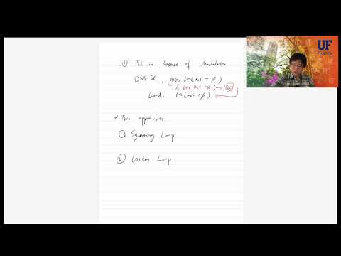
PLL Review: Phase Tracking and FM Demodulation
- A phase-locked loop compares input and VCO output phases, then filters their phase difference to produce an error signal.
- For FM demodulation, the PLL error is proportional to the transmitted message, while the VCO integrates its control input to regenerate the carrier phase.
- The small-error approximation sin(x) ≈ x turns the phase detector output into a scaled phase difference.
- A proportional-integral loop filter, such as K1 + K2/s, can drive steady-state phase error toward zero under the stated assumptions.
4:58
Why PLLs Recover Carriers for Coherent AM Detection
- A PLL can track a received carrier’s phase and generate a locally synchronized carrier for coherent detection.
- Envelope detection can recover conventional AM, but SSB, VSB, and QAM require coherent detection.
- A narrow filter can extract the carrier from transmitted-carrier AM, but DSB-SC suppresses the carrier and provides no direct carrier reference.
- Two carrier-recovery approaches are introduced for DSB-SC: the squaring loop and the Costas loop.
12:30
Squaring Loop: Recovering a DSB-SC Carrier
- Squaring s(t) = m(t)cos(ωct + θi) creates a component proportional to m²(t)cos(2ωct + 2θi), shifting carrier information to twice the carrier frequency.
- A band-pass filter centered at 2ωc selects the doubled-frequency component and removes the baseband m²(t) term.
- A limiter makes the selected carrier’s amplitude approximately constant before it enters the PLL.
- The PLL tracks the doubled phase, and a divide-by-two stage restores a carrier at ωc for coherent demodulation.
20:16
Costas Loop: In-Phase and Quadrature Detection
- The Costas loop splits the received DSB-SC signal into in-phase and quadrature branches using local cosine and sine signals.
- After low-pass filtering, the branches produce terms proportional to m(t)cos(φ) and m(t)sin(φ), where φ is the input-to-local phase error.
- When the phase error approaches zero, the in-phase branch directly provides a scaled version of m(t).
- The quadrature branch supplies the phase-error information needed to correct the local oscillator.
24:40
Costas Loop: Error Generation and VCO Feedback
- Multiplying the filtered in-phase and quadrature outputs yields a loop signal proportional to m²(t)sin(2φ)/8.
- For small φ, sin(2φ) ≈ 2φ, so a narrow low-pass filter extracts a slowly varying error proportional to phase difference.
- That error controls the VCO, closing the feedback loop and aligning the local phase with the received carrier.
- The Costas loop combines carrier recovery and DSB-SC demodulation without the squaring operation used by the squaring loop.
32:06
Superheterodyne Receivers: Fixed Intermediate-Frequency Filtering
- Highly selective, tunable band-pass filters are difficult to build across many radio frequencies, motivating conversion to a fixed intermediate frequency (IF).
- A superheterodyne receiver mixes the selected incoming signal to a standard IF, applies high-Q filtering there, and then detects the signal.
- Typical IF values cited are 455 kHz for AM, 10.7 MHz for FM radio, and 38 MHz for television.
- A fixed, well-designed IF filter can serve channels at different radio frequencies by changing the local oscillator.
37:54
Frequency Mixing and the Superheterodyne Image Problem
- Multiplying a signal at ωc by a local oscillator at ωLO creates components at the sum and difference frequencies.
- With high-side injection, ωLO = ωc + ωIF, the desired signal converts to the IF difference frequency.
- A second, unwanted RF frequency can also mix to the same IF; this interfering frequency is the image frequency.
- An RF band-pass filter rejects the image before mixing, and it need not have the extreme selectivity required of the IF filter.
48:38
Superheterodyne Receiver Signal Path and Image Rejection
- The receiver chain begins with an antenna and RF amplifier that includes a tunable band-pass filter centered on the desired carrier.
- A tunable local oscillator, set relative to the desired carrier and chosen IF, shifts the selected channel to the IF.
- A high-Q IF band-pass filter provides channel selectivity before the signal detector performs coherent or noncoherent demodulation.
- The RF image-rejection filter and local oscillator must track the selected channel together.
50:54
FM Broadcast Radio: Channel Width and Stereo Multiplexing
- FM broadcast radio occupies 88 to 108 MHz, with channels spaced 200 kHz apart, peak frequency deviation of 75 kHz, and roughly 15 kHz message bandwidth.
- Carson’s rule gives an approximate mono FM bandwidth of 2(75 kHz) + 15 kHz = 165 kHz; the lecture rounds this to about 180 kHz.
- Stereo transmission preserves mono compatibility by sending L+R as the mono signal and L−R using DSB-SC around a 38 kHz subcarrier.
- A 19 kHz pilot supports coherent recovery of the 38 kHz subcarrier; RDS and digital OFDM signals can add further information.
56:39
AMPS: Analog Mobile Channels and Frequency-Division Duplexing
- AMPS, the first-generation U.S. mobile phone system, launched in 1983 and used analog FM with 30 kHz channel spacing.
- A 12 kHz peak deviation and 4 kHz voice bandwidth give an approximate 32 kHz FM channel bandwidth by Carson’s rule.
- Frequency-division duplexing separates mobile-to-base uplink channels at 824 to 849 MHz from base-to-mobile downlink channels at 869 to 894 MHz, a 45 MHz separation.
- The 824 to 849 MHz allocation contains 832 channels; 21 channels in each A and B block are reserved for control signaling.
59:00
AMPS Channel Allocation, Control Signaling, and Shutdown
- AMPS divides spectrum into A and B carrier allocations, with separate channel numbering and control channels alongside voice channels.
- The FCC allowed cellular carriers to stop providing AMPS service in 2008, and the last U.S. AMPS signal was turned off around 2011.
- AMPS illustrates how a fixed channel plan supported simultaneous analog calls before later mobile generations replaced it.
1:01:27
Seven-Cell Frequency Reuse and the Move to Digital Communications
- A seven-cell reuse pattern assigns different frequency groups to nearby cells and reuses the same frequencies in cells farther apart.
- Spatial reuse increases system capacity without requiring every cell to have a unique frequency allocation.
- Smaller cells can improve capacity, but require transmit-power adjustments because closer co-channel cells increase interference.
- The lecture closes the analog-communications unit and previews digital communications for the next lecture.
Summary, takeaways, and chapters were generated by AI from the video's transcript and may contain errors. The video belongs to its creator, Mingyue Ji.