EEL4514C Communication Systems and Components, Fall 2026, Lecture 22
 Watch on YouTube →
Overview
Mingyue Ji reviews wideband FM bandwidth and conventional differentiator-based demodulation, then develops the phase-locked loop (PLL) as an FM demodulator. The lecture derives how the PLL’s phase-error signal tracks the message under lock, analyzes the loop with Laplace transforms, and shows why a proportional-integral (PI) loop filter can eliminate steady-state error from both phase and frequency offsets.
Key takeaways
- Carson’s rule estimates FM bandwidth as 2(Δf + B), where Δf is peak frequency deviation and B is message bandwidth; this reduces to roughly 2B for narrowband FM.
- A limiter–differentiator–envelope-detector FM receiver is simple, but differentiation amplifies high-frequency noise and converts the signal into an amplitude-varying form vulnerable to noise.
- A PLL’s phase detector produces a low-pass-filtered signal proportional to sin(θi − θo), which becomes approximately proportional to phase error when the loop is near lock.
- The VCO integrates its frequency-control input, so under close tracking the PLL error is proportional to the derivative of input phase and therefore to the FM message.
- Proportional-only loop control leaves steady-state error when the input has a fixed frequency offset; adding an integrator in a PI loop filter removes that error in the analyzed case.
Chapters
0:00
Wideband FM Bandwidth and Carson’s Rule
- Approximating the message with short rectangular segments creates many sharp transitions, making the estimated FM spectrum and bandwidth pessimistic.
- Peak frequency deviation is Δf = Kf Mp when Mp is the maximum absolute message amplitude.
- Carson’s rule estimates FM bandwidth as approximately 2(Δf + B); with modulation index β = Δf/B, narrowband FM approaches 2B.
4:47
Why Differentiator-Based FM Demodulation Is Noisy
- The conventional demodulator uses a limiter, a band-pass filter around the carrier, a differentiator, and an envelope detector.
- The limiter removes unwanted amplitude variations before differentiation, while the band-pass filter suppresses high-frequency components introduced by sharp limiter transitions.
- Differentiation amplifies high-frequency noise, and the resulting AM-like signal exposes the message to amplitude noise.
7:21
PLL Demodulation: Tracking the Received Carrier Phase
- A PLL’s primary goal is to make its output phase θo track the received phase θi.
- The phase-tracking function also enables FM demodulation: the loop’s error signal becomes related to the rate of change of the tracked phase.
- For an FM input, the instantaneous phase contains the integral of the message, so its derivative recovers a scaled version of that message.
9:35
Phase Detector and Loop Filter Produce Phase Error
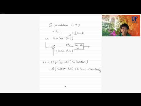
- The input carrier is multiplied by a quadrature local signal generated from the PLL output.
- The product contains a difference-phase term and a high-frequency sum-phase term; a low-pass loop filter removes the latter.
- The remaining detector output is proportional to sin(θi − θo), providing a signal that drives the loop toward phase alignment.
15:03
Small-Error Approximation and the VCO Feedback Loop
- Near lock, the phase error is small, so sin(θi − θo) can be approximated by θi − θo.
- The voltage-controlled oscillator changes its frequency according to ωVCO = ωc + Kv e(t).
- Because VCO phase is the integral of its frequency, the error signal is proportional to the derivative of the output phase.
18:58
Recovering the FM Message from the PLL Error
- When the PLL tracks closely, θo is approximately θi, making e(t) proportional to dθi/dt.
- For FM, differentiating the input phase cancels its message integral and yields a scaled message signal, with the scale determined by PLL and FM gain constants.
- The phase error must remain small but nonzero to provide the control signal that adjusts the VCO.
22:55
Laplace-Domain PLL Model and Error Transfer Function
- The linearized PLL model uses phase-detector gain Kp, loop filter F(s), and VCO transfer function K0/s.
- The closed-loop phase response is formed from the forward-path gain KpK0F(s)/s and feedback, allowing output phase to be compared with input phase.
- The error-to-input transfer function supports loop-filter design by predicting whether phase error settles to zero for a given input.
30:49
Why a PI Loop Filter Handles Frequency Offset
- The test input θ(t) = Δωt + φ0 represents a fixed frequency offset Δω and phase offset φ0; its Laplace transform is Δω/s² + φ0/s.
- With proportional control, F(s) = 1, the steady-state error is nonzero when Δω is nonzero, so proportional control handles phase offset alone.
- A PI filter, F(s) = K1 + K2/s, adds an integrator and yields zero steady-state error for the tested phase and frequency offsets.
Summary, takeaways, and chapters were generated by AI from the video's transcript and may contain errors. The video belongs to its creator, Mingyue Ji.