ECircuits-Lec17-2026
 Watch on YouTube →
Overview
The lecture applies diode models to ESD protection, AC-to-DC rectification, and waveform clipping. It compares half-wave rectification with bridge and center-tap full-wave designs, deriving average outputs of 0.318·Vₘ and 0.636·Vₘ and explaining the diode-drop and input-impedance trade-offs.
Key takeaways
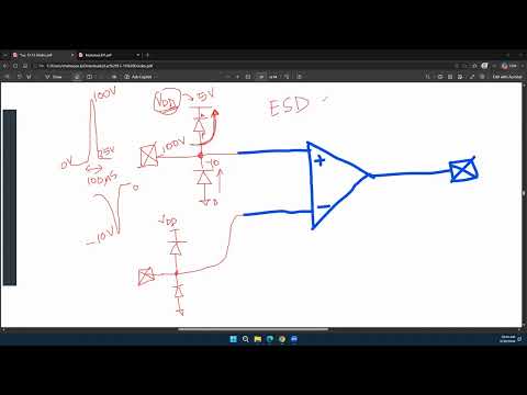
- Connecting protection diodes from an op-amp pin to its supply rails clamps inputs above about VDD + 0.7 V or below about −0.7 V, diverting surge current away from the IC.
- ESD protection has an input-loading cost: reverse-biased clamp diodes can have finite impedance that lowers the effective impedance seen by a high-impedance op-amp input.
- An ideal half-wave rectifier produces an average DC output of Vₘ/π ≈ 0.318·Vₘ; full-wave rectification doubles that value to 2Vₘ/π ≈ 0.636·Vₘ.
- A bridge rectifier requires two conducting diodes per half-cycle, while a center-tap rectifier requires one; with 0.7 V diodes, their path drops are about 1.4 V and 0.7 V, respectively.
- The diode’s peak inverse voltage rating must exceed the largest reverse voltage it experiences, or the diode may enter breakdown.
- A series clipper’s output boundary depends on both diode threshold and any bias source: a 0.7 V silicon threshold shifts the waveform, while a 5 V bias can move the ideal clipping boundary to −5 V.
Chapters
0:00
Real Diode Characteristics: Threshold Voltage and Reverse Leakage
- A real diode conducts strongly after its forward-bias knee, rather than acting as an ideal short circuit.
- Circuit designers can estimate threshold voltage by extending a straight-line approximation of the forward I–V curve to the voltage axis.
- Reverse-biased diodes still carry minority-carrier leakage current, so they are not ideal open circuits.
4:09
Op-Amp Input Protection Against ESD and Supply Transients
- Handling an op-amp IC can expose its pins to electrostatic discharge, since the human body can accumulate hundreds or thousands of volts.
- Input, output, and other IC pins can be protected with diodes connected to the supply rail and ground.
- For a 5 V rail and 0.7 V diode threshold, the upper clamp conducts above about 5.7 V and the lower clamp below about −0.7 V.
- Rail-clamp diodes divert short surges away from sensitive op-amp circuitry, provided the protection diodes can handle the surge current.
13:41
ESD Clamps Trade Input Impedance for Surge Protection
- Between roughly −0.7 V and 5.7 V with 5 V rails, both protection diodes are reverse-biased during normal operation.
- Real reverse-biased diodes have finite impedance, potentially hundreds of kilohms, which can load an op-amp input designed for very high impedance.
- The protection circuit therefore trades reduced susceptibility to voltage surges for lower effective input impedance.
17:03
Half-Wave Rectification: Passing One Half of an AC Cycle
- A series diode and load resistor pass the positive half-cycles of a sinusoidal input and block the negative half-cycles.
- With an ideal diode, the resistor sees the positive input waveform during conduction and approximately zero output during the blocked half-cycle.
- Rectification can supply DC from induced AC, such as power coupled between an external coil and an implanted pacemaker coil.
22:03
Half-Wave DC Output: Averaging and Low-Pass Filtering
- The half-wave output has a positive average because its negative half-cycles are removed; its ideal DC component is Vₘ/π, or about 0.318·Vₘ.
- A low-pass RC filter suppresses the waveform’s changing components and approaches its average value as the cutoff frequency decreases.
- Increasing the RC time constant lowers the filter bandwidth and reduces output ripple, making the result more nearly constant DC.
29:29
Reverse Breakdown Voltage and Peak Inverse Voltage
- A reverse-biased diode has a finite leakage region and can enter breakdown if its reverse voltage becomes too large.
- The diode’s peak inverse voltage rating must exceed the maximum reverse voltage imposed by the AC input.
- For a sinusoidal input with peak amplitude Vₘ, the reverse-voltage rating must safely withstand that peak.
31:22
Four-Diode Bridge Rectifier: Full-Wave Current Paths
- A bridge rectifier uses four diodes so the load current flows in the same direction during both AC half-cycles.
- During each half-cycle, a different pair of diodes conducts; the load polarity remains unchanged.
- A real bridge places two forward-biased diodes in the current path, producing about 1.4 V total drop for 0.7 V diodes.
- The ideal full-wave average is 2Vₘ/π, or about 0.636·Vₘ—twice the ideal half-wave average.
36:08
Center-Tap Transformer Rectification: One Diode Drop per Half-Cycle
- A center-tapped transformer secondary provides two equal voltage halves relative to its grounded midpoint.
- One diode conducts on each half-cycle, and both paths drive current through the load in the same direction.
- The center-tap design has about one 0.7 V diode drop rather than the bridge rectifier’s two drops, which can matter for low-voltage inputs.
- An ideal full-wave output averages 0.636·Vₘ; with real diodes, the center-tap output loses one forward drop.
40:17
Center-Tap Conduction Paths and Rectifier Voltage-Drop Comparison
- On the positive secondary half-cycle, diode D1 conducts through the load to the grounded center tap while D2 is reverse-biased.
- On the negative half-cycle, D2 conducts and D1 is reverse-biased; load current still flows in the same direction.
- The bridge rectifier loses about 1.4 V through two conducting diodes, while the center-tap circuit loses about 0.7 V through one.
- Both full-wave designs have the same ideal average output, about 0.636·Vₘ, before accounting for diode drops.
43:09
Series Diode Clippers and Biased Waveform Thresholds
- A series clipper passes input levels that forward-bias its diode and removes the portions that reverse-bias it.
- With a real silicon diode, a 10 V peak input produces roughly 9.3 V at the output because conduction begins near 0.7 V.
- For triangular and sinusoidal inputs, the 0.7 V crossing points shift the output’s start and stop times as well as its peak.
- Adding a 5 V source with the shown polarity shifts the ideal conduction boundary to −5 V; clamper circuits and BJTs are introduced as upcoming topics.
Summary, takeaways, and chapters were generated by AI from the video's transcript and may contain errors. The video belongs to its creator, WISE Lab - UF ECE.