EAS4200 Aerospace Structures, Lecture 22, 2026 fall
 Watch on YouTube →
Overview
Ting Dong applies Basquin stress-life fatigue analysis, Miner’s cumulative-damage rule, and the Goodman mean-stress correction to a rectangular beam exposed to fully reversed and zero-to-maximum bending cycles. The lecture then introduces crack-growth mechanics, defining stress-intensity range and threshold behavior before presenting the Paris equation for stable crack propagation and the critical condition for fracture.
Key takeaways
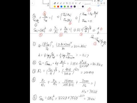
- For the example’s 15,000 fully reversed cycles, the 2-by-10-inch rectangular section and Kf = 1.35 produce a local stress of about 40.5 ksi and an estimated life of about 20,824 cycles.
- Miner’s rule converts the first block’s accumulated damage into an estimated second-block life of about 7,565 cycles when failure occurs after 15,000 first-block cycles and 7,000 second-block cycles.
- A zero-to-maximum bending cycle has equal mean and alternating stresses, so the unknown moment must be solved using the Goodman correction rather than treating the cycle as fully reversed.
- The Paris equation models stable crack growth as da/dN = C(ΔK)^m, while ΔKth marks the approximate onset of growth and KIC marks the critical fracture condition.
- Aircraft crack-management choices depend on both crack size and structural criticality, ranging from a stop-hole to reinforcement or full component replacement.
Chapters
0:00
Fatigue-Life Problems as Design Questions
- Ting Dong extends the prior stress-life example beyond calculating cycles to failure, noting the same equations can solve for allowable force or minimum dimensions.
- The main example asks for an unknown bending moment after a component experiences two different fatigue-cycle types and fails.
1:00
Set Up Two Bending-Fatigue Histories
- The specimen has a rectangular cross-section 2 inches thick by 10 inches high, with bending about the z-axis.
- The first load is fully reversed bending at a moment magnitude of 10^6 in-lb for 15,000 cycles; the second is a released, zero-to-maximum bending cycle for 7,000 cycles.
- The unknown is the second moment, M₂; the given material data include an endurance limit of 30 ksi, ultimate strength of about 120 ksi, and fatigue stress-concentration factor Kf = 1.35.
8:30
Choose Goodman and Avoid Recalculating Given Data
- The second loading has nonzero mean stress, so Dong uses the Goodman equation for the course’s fatigue calculations.
- Because Kf is specified directly as 1.35, there is no need to derive it from a theoretical stress-concentration factor and notch sensitivity.
- For the released cycle, the minimum stress is zero, making the alternating stress and mean stress both half the maximum stress.
14:00
Apply Miner’s Rule to Find the Second-Cycle Life
- Failure after both loading blocks means the Miner damage fractions satisfy n₁/N₁ + n₂/N₂ = 1.
- For the first fully reversed cycle, the local bending stress is calculated using Kf M₁c/I, with c = 5 inches and I = bh³/12.
- Dong calculates a first-cycle stress of about 40.5 ksi and a Basquin life of about 20,824 cycles; with 15,000 cycles applied, Miner’s rule gives a second-cycle life of about 7,565 cycles.
18:00
Solve the Unknown Moment with Goodman Correction
- The 7,565-cycle life implies an equivalent fatigue strength of about 70 ksi for the second loading block.
- The second block’s maximum local stress is expressed as Kf M₂c/I, while its minimum stress remains zero; these determine σa and σm for Goodman.
- Substituting the stress expressions and material strength into Goodman yields an equation in M₂; the same workflow can instead solve for a required cross-section dimension.
27:45
Why Crack Size Adds Information Beyond Stress-Life Analysis
- Stress-life methods estimate fatigue life without explicitly tracking crack size, whereas maintenance decisions often depend on the crack already present.
- Possible aircraft repairs range from drilling a stop-hole for a small crack to installing a reinforcing patch or replacing an entire component.
- Crack size must be considered alongside location and stress criticality, such as distinguishing a landing-gear or wing-root location from a secondary structure.
30:40
Define Crack-Growth Stages and Stress Intensity
- The crack-growth plot relates da/dN, crack extension per cycle, to stress-intensity factor K; crack size is a and cycle count is N.
- The three regimes are crack initiation, stable propagation, and unstable propagation; stable cracks should be monitored so repair occurs before instability.
- Dong gives K = βσ√(πa), where β accounts for geometry, and defines ΔK as the stress-intensity range corresponding to the applied stress range.
40:20
Use the Paris Equation for Stable Crack Growth
- Below the threshold ΔKth, crack growth can be approximated as negligible; above it, growth begins.
- In the stable-propagation region, the log-log relationship is approximated by the Paris equation, da/dN = C(ΔK)^m.
- The third region is unstable propagation: when K reaches the critical stress-intensity value KIC, fracture occurs, so designs and inspections must prevent cracks from reaching that condition.
Summary, takeaways, and chapters were generated by AI from the video's transcript and may contain errors. The video belongs to its creator, Ting Dong.