CE351 lec22 Wrap up the IR tutorial
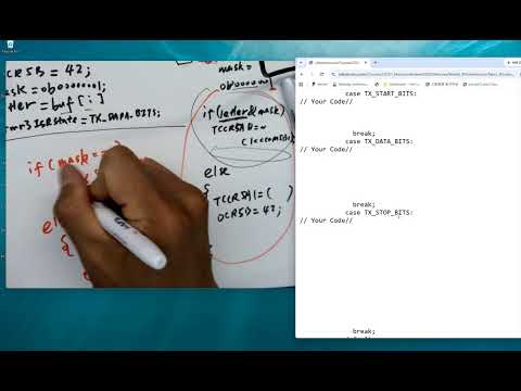 Watch on YouTube →
Overview
Yiyan Li wraps up CE351’s infrared transmitter tutorial by tracing the AVR timer-driven state machine: Timer5 generates IR pulses, while Timer3 advances start, data, and stop-bit states and handles message termination. The lecture also reviews UART baud-rate and receive-interrupt setup, checksum and buffer behavior, and exam-style questions on the implementation.
Key takeaways
- Timer5 generates the IR carrier using its compare-output configuration, and with ICR5 = 420, OCR5B = 42 gives the 10% duty cycle described in the tutorial.
- The transmitter represents each byte with a start bit, eight masked data bits, and a stop bit; a Timer3-driven state machine advances through those parts.
- A null terminator provides a detectable boundary for checksum handling, while an explicit flag can help distinguish the final checksum byte from ordinary message characters.
- UBRR values above 255 must be split between UBRRH and UBRRL; shifting right eight bits selects the high byte, while assignment to UBRRL retains the low byte.
- UART receive interrupts process a complete framed byte, not each incoming bit: the interrupt occurs after the start bit, eight data bits, and stop bit arrive.
- An 8-bit unsigned checksum wraps modulo 256, and the transcript describes it as the sum of the ASCII values of the transmitted characters.
Chapters
0:00
Timer5 PWM Registers for the IR Start Bit
- The IR decoder reports a low when the transmitter pulls the signal down, so the start bit turns the IR output on.
- Timer5 controls the IR carrier through TCCR5A and the compare-output configuration; OCR5B sets the compare value.
- With ICR5 set to 420, OCR5B is set to 42 for a 10% duty cycle.
6:00
Initialize the Transmit State and Current Character
- The idle state waits for the transmit-start condition, then resets the message index and advances to the start-bit state.
- A one-bit mask, initialized as 0b00000001, extracts individual bits from the current character.
- The current character is loaded from the message buffer using its index before the Timer3 state advances.
12:00
Transmit Data Bits with a Mask and IR On/Off Control
- The data state tests the current character with a bitwise AND against the mask to determine the bit being sent.
- A data bit of 1 turns the IR output off; a 0 turns it on using the Timer5 compare-output setup.
- After all eight bits have been shifted through the mask, the state changes to the stop-bit state.
17:00
Stop Bits, Message Termination, and Checksum Handling
- The stop bit pulls the IR output up, completing the start–8-data-bit–stop framing for each transmitted byte.
- After a normal character, the index advances and the next character begins with a new start bit.
- A null terminator identifies the transition to the checksum byte; after the checksum is sent, the state returns to idle.
- A flag can mark that the message terminator was reached and guide the final stop-bit logic; transmit-start must also be cleared when transmission finishes.
27:30
UART Baud-Rate Register and 16-Bit Value Splitting
- The baud-rate equation uses the 16 MHz clock and includes the specified plus-one and minus-one terms; Li notes that the equation will be provided on the exam.
- UBRR is a 16-bit value stored across UBRRH and UBRRL, so the upper byte is obtained by shifting right eight bits.
- Assigning the value to the 8-bit UBRRL register keeps the low byte and discards the upper byte; a shift that is not assigned back does not change the original C variable.
31:00
UART Receive Interrupts Capture Complete Bytes
- UCSRB enables UART receiving and its receive interrupt, while the frame configuration uses eight data bits.
- The receive interrupt fires after a full 10-bit frame—start bit, eight data bits, and stop bit—has arrived.
- The ISR copies the received byte from the UART buffer into the message list at the current index.
33:30
Exam Review: Baud Rate, Checksums, and IR Register Questions
- The review identifies USART1_RX_vect as the receive-interrupt vector and uses the baud-rate equation to calculate UBRR for 2400 baud.
- A Timer3 interval for 2400 bits per second is calculated from the clock rate and desired bit rate.
- The transmit checksum sums character ASCII codes and is stored as an unsigned 8-bit value, so overflow wraps around modulo 256.
- Other review items cover the two address bytes, the Enter key’s carriage-return character, index incrementing, and the null and checksum bytes at the message end.
39:20
Draw the Timer3 Transmit State Machine
- The diagram moves from transmit-idle to TX-start when transmit-start becomes true; the message index is initialized in idle rather than reset for every character.
- TX-start pulls the output low and loads the current character, then TX-data applies the mask and shifts it through eight bits.
- When the mask is exhausted, the state enters TX-stop and either starts another byte or handles the null-terminator and checksum sequence.
- After the checksum, the machine returns to idle and clears the relevant transmit flags.
46:40
Practice Exam Solutions and Timing Guidance
- Li says solutions to the remaining practice-exam problems will be posted on Canvas.
- The practice exam uses questions adapted from the designed exam but approaches the material from different angles.
- Although the exam is planned for 55 minutes, Li says the problem set may be shortened by about 20%; many items require short answers.
Summary, takeaways, and chapters were generated by AI from the video's transcript and may contain errors. The video belongs to its creator, Yiyan Li.