CE351 lec21 IR transmitting and receiving a message
 Watch on YouTube →
Overview
Yiyan Li explains how an IR message is framed, transmitted, and received using UART, with an additive checksum and a null byte to mark the message end. The message contains placeholder source and destination bytes, typed characters, a null terminator, and a checksum; a receive interrupt copies each incoming byte from UART1's UDR1 register into a memory buffer because UART provides no acknowledgment or flow control.
Key takeaways
- The message format uses two placeholder address bytes, user text, a null terminator, and a checksum; all bytes before the checksum contribute to the checksum.
- A null byte provides a reliable message boundary when the receiver does not know the typed message length in advance, and the checksum immediately follows it.
- The additive ASCII checksum detects many transmission errors but can miss errors when altered characters yield the same sum.
- UART receive interrupts capture bytes independently of the main program, but the ISR must copy each byte from UDR1 quickly because this setup has no acknowledgment or flow control.
- Enter completes message construction, S initiates transmission, and R only prints bytes already received by the ISR.
- A UART frame carrying 8 data bits uses 10 transmitted bits when one start bit and one stop bit are included.
Chapters
0:00
Adding an ASCII Checksum to Detect IR Message Errors
- For a message such as ABCD, the checksum is the sum of the characters' ASCII codes, sent as an additional byte.
- The receiver recomputes the sum and compares it with the received checksum; a mismatch indicates likely transmission corruption.
- An additive checksum is not foolproof: different corrupted characters can produce the same total, though Li describes accidental matches as unlikely.
4:00
Building a Message with Addresses, Typed Characters, and a Null Byte
- The message layout is source address, destination address, user-entered characters, a null byte, and a checksum.
- The two address bytes are predefined placeholders in this exercise, but they are included in the checksum along with the message characters.
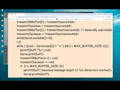
- Pressing M initializes the address bytes and checksum; the character index starts at 2 because those bytes occupy the first two buffer positions.
- Typed characters are echoed to the serial monitor and added to the message buffer and checksum until Enter is pressed or the buffer limit is reached.
12:00
Using Null Termination and UART Receive Interrupts for Message Boundaries
- A null byte marks the end of user-entered content whose length is not known in advance; the following byte is the checksum.
- The program reserves the final two buffer positions for the null byte and checksum, stopping character entry before those positions.
- UART reception triggers an interrupt for each byte, so the receiver must promptly copy each byte into a software buffer before the next arrives.
- UART transmission has no acknowledgment or flow-control mechanism in this setup, so the receiver must keep up with the incoming byte rate.
16:00
Separating Message Construction, UART Transmission, and Display
- Pressing Enter finishes message construction by appending the null byte and checksum; it does not start transmission.
- Pressing S starts transmission of the complete multi-byte message, with a transmission ISR handling the process in the background.
- Pressing R displays data already collected by the receive interrupt; it does not trigger reception.
- The class review notes that a UART byte with 8 data bits uses 10 transmitted bits when the start and stop bits are included.
22:00
How the UART1 Receive ISR Copies Bytes into the Buffer
- The receive ISR runs when a byte arrives, and the received data is available in the UART1 data register, UDR1.
- The ISR stores each byte with an indexed operation such as buffer[index++] = UDR1, advancing the index for the next interrupt.
- The ISR checks incoming data for the null terminator while continuing to store bytes; after the null byte, the next byte is the checksum.
- Li recommends reading the low-level UDR1 register directly in a manually written ISR rather than relying on a higher-level serial-read function.
Summary, takeaways, and chapters were generated by AI from the video's transcript and may contain errors. The video belongs to its creator, Yiyan Li.