CE 312 Lecture 22: Shear/Moment Diagrams VII, Frames & Pre-Derived Analysis Formulas (2026.10.07)
 Watch on YouTube →
Overview
Gregory Michaelson shows that shear and moment diagrams for frames use the same equilibrium and integration principles as beam diagrams, applied member by member with internal forces found at joints. He then explains how pre-derived analysis aids turn routine load cases into reusable formulas, deriving the cantilever-with-uniform-load reactions and the functions V(x) = -wx and M(x) = -wx²/2 while highlighting unit and superposition pitfalls.
Key takeaways
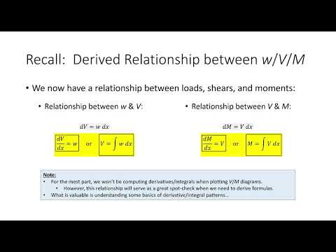
- Frame shear and moment diagrams are constructed member by member using the same equilibrium and shear-to-moment integration rules used for beams; joint cuts reveal the internal force and moment transfers.
- For the example frame, member AB has a 60-kip constant-shear segment and a 600 kip-ft joint moment, while member BC has shear levels of +30 and -45 kips and reaches a 900 kip-ft moment before returning to zero.
- Reversing a member’s node order preserves shear and moment magnitudes but flips diagram signs, so software output should be interpreted with the member’s node numbering in mind.
- A cantilever of length L under uniform load w has support reaction wL, fixed-end moment wL²/2, and cut functions V(x) = -wx and M(x) = -wx²/2 for the stated sign convention.
- Pre-derived formulas require dimensionally consistent inputs; for a triangular load, W may represent the total load resultant rather than the peak intensity.
- When multiple load cases act together, sum their moment functions and find the maximum of the combined function; adding separate maximum values can be wrong when their peaks occur at different locations.
Chapters
0:00
Exam Results, Homework Corrections, and Truss Project Checklist
- Gregory Michaelson reports a strong exam average, including roughly six perfect scores; students will receive emailed deduction details and can collect exams outside his office.
- Homework 5.2 mistakenly listed problem 5.11 instead of 5.31, so everyone receives full credit for the misassigned problem.
- Truss Submittal 1 is due Monday, October 12; include three dimensioned truss elevations, verify the vertical envelope and member-length limit, and place a bottom joint at midspan for the later deflection check.
- The new homework is due Wednesday rather than Monday because Submittal 1 is due Monday; a PDF is acceptable for the project.
6:20
Frame Diagrams: Cut at Joints and Analyze Members Separately
- The method for frame shear and moment diagrams is essentially unchanged from beams; the main difference is that members can be oriented vertically or in other directions.
- Michaelson analyzes each frame member independently, typically cutting at every joint and finding the internal horizontal force, vertical force, and moment there.
- At a joint where multiple members meet, the member-end forces should cancel when the pieces are reassembled, leaving joint equilibrium.
11:00
Member AB: Find the Internal Forces at Joint B
- For the 20-ft column AB, a 60-kip horizontal load and an opposing 60-kip reaction cancel in the horizontal direction.
- Vertical equilibrium gives a 30-kip downward force at B on member AB.
- Taking moments about B balances the 60-kip loads acting at 20 ft and 10 ft, producing a 600 kip-ft internal moment at the cut.
18:11
Member AB: Construct the Vertical Shear and Moment Diagrams
- Michaelson traces the column from A upward to B, using alphabetical joint order as a consistent diagram direction.
- The shear diagram steps from zero to 60 kips, stays constant between loads, then returns to zero.
- Integrating the constant 60-kip shear gives a linear moment segment; the 600 kip-ft concentrated moment at B closes the diagram.
- Reversing the node order would preserve the values but reverse the diagram signs, a detail to watch in structural software such as MASTAN.
24:36
Member BC: Joint-B Forces and Beam Diagrams
- For member BC, vertical equilibrium gives a 30-kip upward force at B; horizontal force at B is zero.
- Moment equilibrium using the 75-kip load at 10 ft and 45-kip roller reaction at 30 ft gives a 600 kip-ft end moment, equal in magnitude and opposite in sign to the member AB cut moment.
- The BC shear diagram starts at 30 kips, drops by 75 kips to -45 kips, and returns to zero at the support.
- The moment diagram includes the 600 kip-ft jump at B, rises to 900 kip-ft, then returns to zero; putting the two cut faces together cancels their equal-and-opposite joint forces and moments.
31:40
Why Engineers Use Pre-Derived Analysis Aids
- Michaelson distinguishes classroom problems, which build analytical skill, from routine real-world beam models that often use simpler, repeated load cases.
- Rather than re-deriving diagrams for every numerical case, engineers can use pre-derived expressions from references such as the American Wood Council timber design supplement or the AISC Steel Manual.
- For a cantilever of length L under uniform load w, the maximum shear magnitude is wL and the fixed-end moment magnitude is wL²/2.
- Analysis aids can provide full shear and moment functions as well as maximum values, supporting plots and checks along the entire member.
35:00
Analysis-Aid Pitfalls: Units, Resultants, and Combined Loads
- Keep units consistent when plugging into formulas; a load in kips per foot cannot be mixed directly with a length in inches.
- For a triangular load increasing to 2.5 kips/ft over a 40-ft span, the symbol W in the cited aid denotes the total resultant, 50 kips—not the peak intensity of 2.5 kips/ft.
- Check formula dimensions: a reaction must have force units, so an answer in kips per foot signals that the inputs or interpretation are wrong.
- For combined loads, add the moment functions and locate the maximum of the sum using calculus or an Excel plot; individual maximum moments may occur at different positions.
40:47
Derive Cantilever Uniform-Load Reactions Symbolically
- Replace a uniform load w over length L with its resultant wL acting at L/2 from the fixed support.
- Vertical equilibrium gives an upward support reaction of wL.
- Moment equilibrium gives the fixed-end reaction moment wL × L/2 = wL²/2.
- These symbolic results apply to any cantilever length and uniform load intensity, avoiding repeated statics calculations.
43:59
Derive V(x) and M(x) for the Cantilever Load Case
- The cantilever shear diagram decreases linearly from zero to magnitude wL, so the maximum shear magnitude is wL.
- Integrating shear gives a parabolic moment diagram with maximum magnitude wL²/2 and the corresponding fixed-end moment jump.
- At a cut distance x from the free end, the uniform load resultant is wx acting at x/2; equilibrium yields V(x) = -wx and M(x) = -wx²/2 under the stated sign convention.
- These functions can drive a reusable spreadsheet template for cantilevers of different lengths and uniform load intensities.
Summary, takeaways, and chapters were generated by AI from the video's transcript and may contain errors. The video belongs to its creator, Gregory Michaelson.