CE 312 Lecture 21: Shear/Moment Diagrams VI, Internal Hinges (2026.10.05)
 Watch on YouTube →
Overview
Gregory Michaelson explains how internal indeterminacy formulas apply to beams and frames, then shows that an internal hinge affects reaction calculations but not the usual construction of shear and moment diagrams. For an 80-ft beam carrying a 3-kip/ft distributed load and a 90-kip point load, he uses the hinge’s zero-moment condition to find reactions of 300 kips at A, 30 kips at B, and a 11,700-ft-kip moment at A, then checks the diagrams against equilibrium and the hinge condition.
Key takeaways
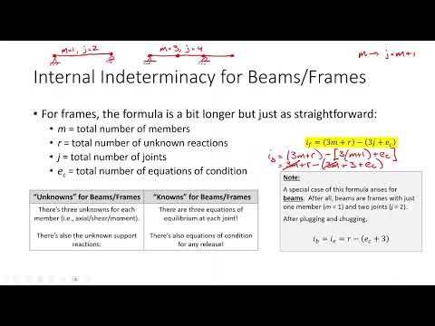
- For a beam or frame, internal indeterminacy can be counted as I_f = 3m + r − 3j + e_c; because a beam has j = m + 1, this reduces to r − e_c + 3.
- An internal hinge contributes the condition that its bending moment is zero; use that condition to solve reactions, then construct the diagrams using the standard load–shear–moment relationships.
- On the 80-ft example beam, the 3-kip/ft load over the 20-ft segment to the right of the hinge becomes a 60-kip resultant 10 ft from the hinge, yielding B_y = 30 kips.
- The full-beam equilibrium solution is A_y = 300 kips upward, B_y = 30 kips upward, and a 11,700-ft-kip fixed-support moment at A; the horizontal reaction is zero.
- The hinge-section calculation gives +30 kips shear, matching the shear diagram at the hinge, while the moment diagram reaches zero there.
- A completed diagram provides independent checks: shear should return to zero at the beam’s end, and moment should satisfy both end conditions and the hinge’s zero-moment condition.
Chapters
0:00
Course Updates, Exam Timing, and Upcoming Beam Deflections
- Gregory Michaelson says Exam 1 grading will be returned on Wednesday and notes that attendance grades are largely current.
- He plans to correct and repost a homework solution that accidentally addressed the wrong problem.
- The next exam is scheduled for October 26, with review on October 23; the next course topic after shear and moment diagrams is beam and frame deflections.
4:20
Internal Indeterminacy Formulas for Frames and Beams
- For a frame, Michaelson presents internal indeterminacy as unknowns minus knowns: I_f = 3m + r − 3j + e_c, with three internal-force unknowns per member and three equilibrium equations per joint.
- The three member unknowns are axial force, shear, and bending moment; the equation applies to beams and frames.
- A beam has j = m + 1, so the frame expression reduces to r − e_c + 3, the same expression as external indeterminacy.
- Michaelson notes that the FE reference manual lists two indeterminacy expressions rather than a separate beam formula.
14:21
An Internal Hinge Changes Reactions, Not Diagram Construction
- The hinge supplies an equation of condition: the internal bending moment at the hinge is zero.
- Use that condition when solving the support reactions; once those reactions are found, construct the shear and moment diagrams with the usual load–shear–moment rules.
- A correctly constructed moment diagram should return to zero at the internal hinge.
17:10
Set Up the 80-Foot Beam and Cut at the Hinge
- The example beam is 80 ft long, carries a uniform 3-kip/ft load across its span, and has a 90-kip point load 50 ft from A.
- The internal hinge is 60 ft from A, leaving 20 ft between the hinge and roller support B.
- Michaelson identifies the fixed-support reactions at A and the vertical reaction at B, and notes that the horizontal reaction at A is zero because there are no horizontal loads.
- For the right-side section cut at the hinge, replace the 3-kip/ft load over 20 ft with a 60-kip resultant acting 10 ft from the cut.
24:10
Use the Hinge Condition to Solve Support Reactions
- Taking moments about the hinge on the 20-ft right segment gives B_y = 30 kips upward from 60 × 10 = B_y × 20.
- The full-span distributed load totals 240 kips, acting 40 ft from A; together with the 90-kip load, total downward load is 330 kips.
- Vertical equilibrium gives A_y = 300 kips upward, while moment equilibrium about A gives a support moment of 11,700 ft-kips.
- The hinge-section free-body diagram also gives a positive internal shear of 30 kips, which later provides a check on the shear diagram.
31:10
Construct the Shear Diagram from Reactions and Loads
- Start at A with a +300-kip shear and decrease linearly by 3 kips/ft to +150 kips at the 50-ft point load.
- The 90-kip point load causes a downward jump from +150 to +60 kips.
- Continue the 3-kip/ft linear decrease to −30 kips at B, then jump upward by B_y = 30 kips to finish at zero.
- At the hinge 60 ft from A, the diagram gives +30 kips, matching the section-cut calculation.
40:50
Use Shear-Diagram Areas to Track Moment Changes
- From A to the point load, the shear-diagram trapezoid has area 225 × 50 = 11,250 ft-kips.
- Between the point load and B, the shear crosses zero 10 ft after the point load, separating positive and negative triangular areas.
- The positive and negative 150-ft-kip triangles cancel; the remaining areas confirm the diagram’s overall change and support the reaction calculation.
44:34
Plot the Moment Diagram and Confirm Zero Moment at the Hinge
- Begin the moment diagram at −11,700 ft-kips at A; adding the 11,250-ft-kip area from A to the point load gives −450 ft-kips there.
- The moment curve is parabolic under the uniform load, rises through zero at the hinge, reaches +150 ft-kips where shear crosses zero, and returns to zero at B.
- The hinge is at the zero-moment point, demonstrating that the solved reactions satisfy the hinge’s internal condition.
47:50
Validate the Reactions with Diagram Closure and the Hinge Check
- The shear diagram begins and ends at zero, confirming vertical equilibrium for the 300-kip, 90-kip, and 30-kip reaction contributions alongside the distributed load.
- The moment diagram also closes at zero and independently reaches zero at the internal hinge.
- Michaelson emphasizes that diagram closure and the hinge’s zero moment together verify the reaction solution.
Summary, takeaways, and chapters were generated by AI from the video's transcript and may contain errors. The video belongs to its creator, Gregory Michaelson.