*CE 312 Lecture 20: Shear/Moment Diagrams V, Conc. Moments & Fixed Supports (2026.10.02)
 Watch on YouTube →
Overview
Gregory Michaelson demonstrates how concentrated couples and fixed-support reactions modify shear and moment diagrams without changing the standard load–shear–moment relationships. Across two beam examples, he shows that a concentrated moment leaves the shear diagram unchanged but creates a jump in the moment diagram, while a cantilever’s fixed-end moment balances the net area under its shear diagram.
Key takeaways
- A concentrated couple does not alter a beam’s shear diagram; it creates a vertical jump in the moment diagram equal to the couple’s magnitude and sign.
- For Michaelson’s first example, the shear areas sum to −20 ft-kips, so the 20 ft-kip couple at D supplies the missing moment change.
- A uniformly distributed load of 3 kips/ft over 10 ft changes shear by 30 kips, producing a linear segment in the shear diagram.
- An inclined 10-kip load must be resolved into its 8-kip vertical component for shear and bending-moment diagrams; its 6-kip horizontal component belongs in the axial-force analysis.
- For the cantilever example, shear areas of +280 and +200 ft-kips total +480 ft-kips, balanced by the fixed support’s opposite 480 ft-kip reaction moment.
Chapters
0:00
Concentrated Moments: No Shear Change, but a Moment-Diagram Jump
- Michaelson reviews that the usual graphical relationships between load, shear, and moment still apply when concentrated couples are present.
- A concentrated moment is not a force, so it produces no jump or other change in the shear diagram.
- Its effect appears in the moment diagram as a vertical jump that accounts for any imbalance in the areas under the shear diagram.
2:40
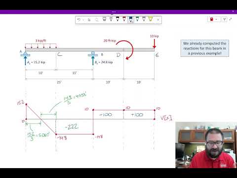
A 20 ft-kip Couple Adds a Jump to the Moment Diagram
- For the previously analyzed beam, the support reactions are 15.2 kips upward at A and 24.8 kips upward at B.
- A 3 kip/ft distributed load over 10 ft reduces shear from +15.2 to −14.8 kips; the 20 ft-kip couple at D does not affect the shear plot.
- The shear-area contributions are +38.51, −36.51, −222, +100, and +100 ft-kips, totaling −20 ft-kips before the couple is included.
- The moment diagram therefore jumps by 20 ft-kips at D, bringing the accumulated moment back to zero at the beam’s end.
13:25
Resolve the Cantilever’s Inclined Load and Plot Axial Force Separately
- Michaelson resolves a 10-kip inclined load into an 8-kip vertical component and a 6-kip horizontal component.
- Only vertical forces enter the shear diagram: the 6-kip axial load and its 6-kip reaction do not affect shear or bending moment.
- Between A and B, the beam carries 6 kips of compression; with compression defined as negative, the axial-force diagram is −6 kips there and zero beyond B.
- The cantilever example also includes a 28-kip vertical reaction, a 20-kip end load, and a 480 ft-kip fixed-support moment.
18:23
The Fixed-End Moment Balances the Cantilever’s Shear Areas
- The cantilever shear diagram steps from zero to +28 kips, drops to +20 kips after the 8-kip vertical load, and returns to zero at the 20-kip end load.
- Its rectangular shear areas are +280 ft-kips over 10 ft and +200 ft-kips over 10 ft, for a total of +480 ft-kips.
- The fixed-support reaction supplies an opposite 480 ft-kip moment, shown as a downward jump in the moment diagram.
- The moment then rises with the positive shear areas and returns to zero at the free end; Michaelson identifies internal hinges as the next topic.
Summary, takeaways, and chapters were generated by AI from the video's transcript and may contain errors. The video belongs to its creator, Gregory Michaelson.