Princeton Intro to Robotics (Fall 2026) | Lecture 4: Quadrotor Dynamics
 Watch on YouTube →
Overview
The lecture connects geometric motion planning to dynamic feasibility by deriving the planar quadrotor’s equations of motion and showing how to express them as a first-order state-space system. It extends the framework to a 12-dimensional 3D quadrotor state, defines a space-fixed XYZ Euler-angle convention and motor thrust/torque models, then outlines the upcoming RRT lab and its safety procedures.
Key takeaways
- A collision-free geometric path is not necessarily executable: quadrotor thrust acts along the body’s vertical axis, so sideways motion requires tilting and sharp turns may exceed the drone’s capabilities.
- For the planar quadrotor, total thrust u₁ = f₁ + f₂ and torque u₂ = l(f₂ − f₁) reduce the model to ẍ = −u₁ sin θ/m, ÿ = u₁ cos θ/m − g, and θ̈ = u₂/I.
- Adding velocities to the three planar configuration variables creates a six-dimensional state; in general, n second-order motion equations become 2n first-order equations.
- The course’s 3D convention is space-fixed XYZ Euler angles—roll φ, pitch θ, yaw ψ—and consistency matters because mixing orientation conventions can break a dynamics model.
- A quadrotor’s 12-dimensional state combines six pose variables with translational and angular rates; its four motor thrusts are commonly reorganized as total thrust plus three body-axis moments.
- The motor model fᵢ = kFωᵢ² can be calibrated with a scale, but the drone must be elevated to avoid propeller-wash errors; yaw is generated by imbalancing drag from counter-rotating propellers.
Chapters
0:00
Why Geometric Paths May Be Dynamically Infeasible
- Geometric planners such as A* and RRT can return collision-free paths that a physical drone cannot execute.
- Tight turns, abrupt direction changes, and narrow passages can exceed a drone’s maneuvering or thrust constraints.
- A level quadrotor cannot translate purely sideways because its propellers generate thrust perpendicular to the body.
- Later lectures will address model errors and disturbances such as unpredictable outdoor wind using feedback control.
4:24
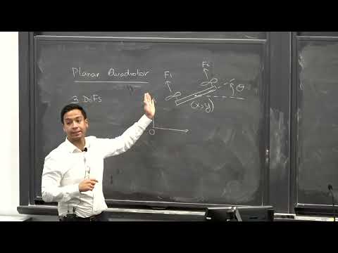
Planar Quadrotor: Three Degrees of Freedom and Two Thrust Inputs
- The planar model represents a front-view quadrotor, effectively a birotor constrained to one plane.
- Its configuration is described by center-of-mass coordinates x and y and orientation θ.
- The two propeller thrust forces are f₁ and f₂; the model initially treats them as directly controllable inputs.
7:14
Newton’s Second Law for Planar Translation and Rotation
- Newton’s second law gives horizontal acceleration ẍ = −(f₁ + f₂) sin θ / m and vertical acceleration ÿ = (f₁ + f₂) cos θ / m − g.
- The thrust components change with the drone’s tilt, while gravity contributes the −g term in the vertical equation.
- Rotational acceleration is determined by the net propeller moment divided by the drone’s moment of inertia I.
11:25
Combine Propeller Forces into Total Thrust and Torque
- The compact input u₁ = f₁ + f₂ represents total thrust.
- The rotational input u₂ = l(f₂ − f₁) represents torque, where l is the distance from the center of mass to a propeller.
- With these inputs, the planar equations become ẍ = −u₁ sin θ / m, ÿ = u₁ cos θ / m − g, and θ̈ = u₂ / I.
13:22
Convert the Planar Model into Six First-Order Equations
- Define velocity variables vₓ = ẋ, vᵧ = ẏ, and angular velocity ω = θ̇.
- The second-order equations become six first-order equations: three relate positions and angle to their rates, and three specify accelerations.
- In general, converting n second-order equations produces 2n first-order equations.
18:51
State-Space Form Predicts Future Quadrotor Motion
- The planar state is X = (x, y, θ, vₓ, vᵧ, ω), and the input is U = (u₁, u₂).
- The dynamics have the general form Ẋ = f(X, U), with mass m, inertia I, and gravity g as model parameters.
- Given an initial state and a sequence of control inputs, integrating the equations predicts the drone’s future state.
- The coordinates x, y, and θ are configuration variables; adding velocities makes the full state sufficient for the dynamics.
25:52
Extending the Dynamics Framework to a 3D Quadrotor
- A 3D quadrotor has six degrees of freedom: three translational coordinates and three orientation coordinates.
- The lecture emphasizes the general first-order form Ẋ = f(X, U), rather than deriving every lengthy 3D equation.
- Students are expected to use supplied equations of motion for planning and control, not derive the complete 3D model in this course.
27:03
Describe Drone Orientation with Space-Fixed XYZ Euler Angles
- The inertial frame is fixed to the room; the body frame is attached to the drone, with forward x, left y, and up z forming a right-handed coordinate system.
- The course uses a space-fixed 1-2-3 sequence: rotate about inertial x by roll φ, inertial y by pitch θ, then inertial z by yaw ψ.
- Right-hand-rule signs apply; under this convention, positive pitch tilts the drone downward.
- Three Euler angles can represent an arbitrary orientation, though different angle triples may describe the same physical orientation.
35:19
Euler-Angle Conventions and the Cost of Mixing Them Up
- Space-fixed rotations use inertial axes, while body-fixed conventions rotate about axes that move with the drone.
- Many valid axis sequences exist; the course consistently uses space-fixed XYZ to avoid ambiguity.
- Mixing angle conventions can invalidate a dynamics model: a motion-capture convention mismatch once cost the lecturer months of work on an airplane model.
- Quaternions are another orientation representation, but the course uses Euler angles for simplicity.
40:23
The 12-Dimensional Quadrotor State and Four Motor Inputs
- Six degrees of freedom yield six second-order equations and therefore a 12-dimensional first-order state.
- The state includes position (x, y, z), Euler angles (φ, θ, ψ), translational velocity, and angular velocity.
- Body angular rates p, q, and r are used instead of Euler-angle rates because they make the equations more convenient; the two representations can be converted using the orientation.
- The four propeller thrusts can be grouped into total thrust and three moments about the body x, y, and z axes.
48:27
Motor Model: Calibrating Thrust from Propeller Speed
- The motor command controls propeller rotational speed; thrust is modeled as fᵢ = kFωᵢ², where kF is the thrust coefficient.
- A practical calibration measures thrust with a digital scale while sweeping propeller speed and fitting thrust against ω².
- Propeller wash can corrupt scale readings by recirculating air, so the drone should be raised above the scale.
- The model assumes sufficiently similar motors and simplifies aerodynamics, but is useful for basic drone control.
54:26
How Counter-Rotating Propellers Produce Yaw Torque
- Adjacent propellers spin in opposite directions, balancing reaction torques when the drone is not yawing.
- Changing motor speeds creates an imbalance in aerodynamic drag and turns the drone about its vertical axis.
- The propeller drag moment is modeled as proportional to squared speed, with a separate moment coefficient.
- Propeller blade pitch is matched to rotation direction so all four rotors produce positive thrust.
59:00
RRT Lab, Flight-Space Access, and Drone Safety
- The upcoming lab implements RRT using a manually measured obstacle map, then sends the drone from a marked start to a goal box.
- The lab focuses on mapping, waypoints, and flight; it assumes the drone’s built-in controller can follow the planned path.
- Students can use the G109 netted space, with four drones, or the smaller F-wing robotics lab, with three; access requires online EHS safety training.
- Teams should take turns organically, report numbered drone faults on the course discussion thread, wear safety glasses, and stay outside the net while a drone flies.
- Each drone costs about $600, so students are asked to handle the shared equipment carefully and never step on it.
Summary, takeaways, and chapters were generated by AI from the video's transcript and may contain errors. The video belongs to its creator, Introduction to Robotics @ Princeton.