L11 - CNOT, SWAP, Phase Shift, Toffoli, Transformation a Matrix
 Watch on YouTube →
Overview
Hiu-Yung Wong develops the matrix and circuit representations of CNOT, SWAP, phase-shift, controlled-phase, and Toffoli gates, deriving their actions from computational-basis states. He also explains phase versus global phase, hardware connectivity constraints, bit-ordering conventions, and the basis-change rule for operators, U′ = MUM†.
Key takeaways
- CNOT’s defining rule, |a,b⟩ → |a,a XOR b⟩, directly yields its matrix: it exchanges |10⟩ and |11⟩ while fixing |00⟩ and |01⟩.
- SWAP is both a two-qubit state permutation and a practical routing tool: fixed-connectivity hardware can use SWAPs to bring distant qubits together before applying a gate.
- The phase-shift gate P(φ) = diag(1,e^{iφ}) preserves normalization but changes the relative phase of |0⟩ and |1⟩, enabling interference effects in quantum algorithms.
- A controlled phase shift has matrix diag(1,1,1,e^{iφ}); only the joint control-and-target state |11⟩ receives the phase.
- The Toffoli gate is a doubly controlled NOT: it swaps |110⟩ and |111⟩ and leaves the other six three-qubit basis states unchanged.
- For an orthonormal basis change defined by Mᵢⱼ = ⟨i′|j⟩, state coordinates transform as s′ = Ms and operator matrices as U′ = MUM†.
Chapters
0:00
Midterm Preparation: Use AI to Learn, Not Just Finish Assignments
- The midterm is in two weeks, and Hiu-Yung Wong urges students to review course concepts and complete assignments themselves.
- Using ChatGPT is acceptable, but replacing study with quick answers can leave students unable to solve problems from scratch.
- A suggested practice method is to ask AI to generate additional questions, then solve them independently while preserving study time.
3:04
NOT Gates and Tensor Products for Two Qubits
- A one-qubit NOT gate is defined by swapping the computational basis states |0⟩ and |1⟩.
- Applying NOT independently to both qubits requires a tensor product, expanding the state space from dimension 2 to dimension 4.
- For a two-qubit state with amplitudes α, β, γ, δ, applying NOT to both qubits reverses the amplitudes to δ, γ, β, α.
5:55
CNOT as XOR on the Target Qubit
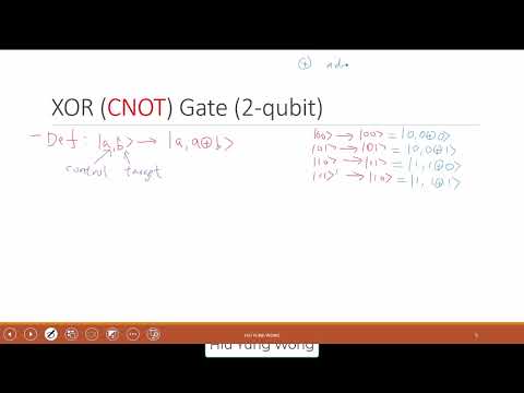
- CNOT maps a basis state |a,b⟩ to |a, a XOR b⟩, with a and b each equal to 0 or 1.
- The first qubit is the control and remains unchanged; the second is the target and flips only when the control is 1.
- XOR is also addition modulo 2: 1 XOR 1 = 0 because 1 + 1 leaves remainder 0 modulo 2.
12:06
CNOT Matrix, State Amplitudes, and Circuit-Wire Conventions
- In the ordered basis |00⟩, |01⟩, |10⟩, |11⟩, CNOT leaves the first two basis states fixed and swaps |10⟩ with |11⟩.
- Its matrix is [[1,0,0,0],[0,1,0,0],[0,0,0,1],[0,0,1,0]], so it maps amplitudes (α,β,γ,δ) to (α,β,δ,γ).
- In a circuit symbol, the filled dot marks the control and the NOT target is shown on the other wire; the control can be drawn above or below the target.
- Hiu-Yung Wong warns that wire position and most-significant-bit ordering depend on the architecture and diagram convention; he follows the IBM-style convention discussed in class.
20:53
Reversed Controls and Zero-Controlled Gates
- CNOT can use the second qubit as control and the first as target, giving |a,b⟩ → |a XOR b,b⟩.
- A controlled operation may also activate when its control is 0 rather than 1; a hollow circle denotes this zero-control convention.
- To derive a reversed-control matrix, identify which basis states have the activating control value and determine which target-state pairs are exchanged.
23:03
SWAP Gate: Moving Quantum States Between Connected Qubits
- SWAP maps |a,b⟩ to |b,a⟩, exchanging the states held by two qubits while leaving |00⟩ and |11⟩ unchanged.
- Its matrix preserves the first and fourth basis states and exchanges the second and third; a state with amplitudes (α,β,γ,δ) becomes (α,γ,β,δ).
- On fixed-layout hardware such as superconducting or silicon-spin systems, SWAP gates can bring nonadjacent qubits together for an otherwise unavailable interaction.
- Trapped-ion or neutral-atom platforms may instead move qubits or support longer-range interactions, depending on the architecture.
30:15
Reading SWAP Matrices Without Confusing MSB and LSB
- Matrix rows select which input amplitudes contribute to each output component; Wong reads them as filters applied to the state vector.
- A SWAP changes which value occupies each bit position, not the definition of the most- and least-significant positions.
- Keeping a consistent basis order prevents mistakes when interpreting matrices and comparing circuit diagrams.
32:57
Single-Qubit Phase Shift: P(φ) Adds Phase to |1⟩
- The phase-shift gate is P(φ) = diag(1,e^{iφ}): it leaves |0⟩ unchanged and maps |1⟩ to e^{iφ}|1⟩.
- Euler’s identity gives e^{iφ} = cos φ + i sin φ, whose magnitude is 1, so the gate preserves the state’s normalization.
- For α|0⟩ + β|1⟩, the output is α|0⟩ + βe^{iφ}|1⟩.
36:25
Relative Phase, Global Phase, and Quantum Interference
- Multiplying an entire state by e^{iφ} creates a global phase, which does not change its physical predictions.
- A phase shift applied only to the |1⟩ component changes the relative phase between |0⟩ and |1⟩.
- Relative phase matters because quantum algorithms use phase differences to produce constructive and destructive interference.
- A phase on |0⟩ can be represented, up to a global phase, by applying an appropriate negative phase shift to |1⟩.
39:31
Deriving Phase-Shift Matrix Elements and Identifying Pauli Z
- A matrix element can be computed as ⟨i|U|j⟩, using the output of U on basis vector |j⟩ and projecting onto basis vector |i⟩.
- Setting φ = π gives e^{iπ} = −1, so P(π) = diag(1,−1), the Pauli Z gate.
- Pauli Z maps |+⟩ to |−⟩ and |−⟩ to |+⟩; in the plus/minus basis, it acts like a NOT gate.
48:22
Controlled Phase Shift and the Four-Basis-State Matrix
- A controlled phase shift applies P(φ) to the target only when the control qubit is 1; otherwise it applies the identity.
- For |00⟩, |01⟩, and |10⟩, the state is unchanged; |11⟩ acquires the factor e^{iφ}.
- The two-qubit matrix is diag(1,1,1,e^{iφ}), since only the final computational-basis state receives a phase.
- A filled control dot conventionally means activation on 1, while a hollow circle signals activation on 0.
57:59
Toffoli Gate: Two Controls Flip the Third Qubit
- The Toffoli gate maps |a,b,c⟩ to |a,b,c XOR (a AND b)⟩, leaving both control qubits unchanged.
- The target flips only when both controls are 1; for the other six three-qubit basis states, the gate does nothing.
- In the ordered basis |000⟩ through |111⟩, the matrix is identity on the first six states and swaps |110⟩ with |111⟩.
1:04:17
Changing State Coordinates with a Basis-Transformation Matrix
- For old basis {|j⟩} and new basis {|i′⟩}, define Mᵢⱼ = ⟨i′|j⟩.
- If s is a state vector’s coordinate column in the old basis, its new-basis coordinates are s′ = Ms.
- The same procedure applies when the new basis is a different set of states, such as the plus/minus basis.
1:07:04
Transforming a Gate Matrix: U′ = MUM†
- An operator represented by U in the old basis is represented in the new basis by U′ = MUM†.
- The relation follows from s′ = Ms and the requirement that applying the operation and changing coordinates give the same result in either order.
- Equating the action on any state gives U′M = MU; multiplying on the right by M† yields the change-of-basis formula when M is unitary.
1:13:13
Why Basis-Change Matrices Are Unitary
- When both bases are orthonormal, M’s columns are the new-basis coordinate representations of the old basis vectors.
- Those columns form an orthonormal set, so M is unitary and satisfies MM† = I.
- The lecture ends by asking students to work through why orthonormal basis vectors guarantee this property.
Summary, takeaways, and chapters were generated by AI from the video's transcript and may contain errors. The video belongs to its creator, Quantum Computing, TCAD, Semicond by Hiu-Yung Wong.