ENGR 201 Fall 2026 - Lecture 07: 2D Moment
 Watch on YouTube →
Overview
Bruno Guidio, PhD, introduces 2D moments in statics, explaining how force location and body size matter when a rigid body can no longer be modeled as a particle. He develops the signed moment calculation, M_O = Fd, through perpendicular-distance diagrams, force components, and multi-force examples, using counterclockwise as positive and clockwise as negative.
Key takeaways
- For a force F about point O, moment magnitude is F times the shortest perpendicular distance from O to the force's line of action; the arrow's endpoints do not define the lever arm.
- A force whose line of action passes through the reference point has zero moment about that point, even if the force is large.
- With the lecture's sign convention, counterclockwise moments are positive and clockwise moments are negative; this sign is independent of the force's Cartesian direction.
- For an angled force on a horizontal bar, resolving it into horizontal and vertical components can simplify moment calculations because each component pairs with a clear perpendicular distance.
- Moments about multiple forces must be added algebraically, preserving each force's sign; the four-force example totals approximately +56.57 N·m.
- Changing the reference point changes lever arms and may change both the magnitude and sign of individual moments, so every moment calculation must specify its point of reference.
Chapters
0:00
Course Schedule and the Shift from Particle Models
- Homework 3 was due the previous night; the current assignment is due Tuesday rather than Monday.
- The course will cover 2D moments first, 3D moments on Thursday, then a new topic and an exam review before Exam 1 in early October.
- Earlier particle problems ignored body size, but rigid-body analysis must account for force locations and the body's dimensions.
2:20
Why Force Location Matters for Rigid Bodies
- A person sitting at different positions on a table produces different effects because the load acts at different locations.
- A force applied away from a support can create a tendency to rotate the body, unlike a model that treats all forces as acting at one point.
- Moment analysis extends force-based engineering problems to bodies whose size and geometry matter.
5:30
Moment as a Force's Tendency to Rotate a Body
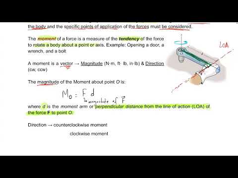
- Moment is defined as the tendency of a force to rotate a body about a point, such as point O.
- A door illustrates the concept: pushing at a location away from its hinges tends to rotate it about the hinge axis.
- Moment is a vector quantity with a magnitude and a rotational direction.
8:34
Moment Magnitude and Perpendicular Distance
- The magnitude of a moment about O is calculated as M_O = Fd, where F is force magnitude and d is the perpendicular distance.
- Distance d is measured at 90 degrees from the force's line of action to point O—not from the arrow's tail, tip, or midpoint.
- The same force can produce different moments about different reference points because the perpendicular distance changes.
11:14
Sign Convention: Counterclockwise Positive
- Guidio adopts counterclockwise rotation as positive and clockwise rotation as negative.
- The sign describes the force's rotational effect about the chosen point, not whether the force points up, down, left, or right.
- Moment units combine force and distance, such as newton-meters (N·m), not newtons per meter.
15:39
A 10 N Force at 4 m Produces −40 N·m
- For a 10 N vertical force with a 4 m perpendicular offset from O, the moment magnitude is 10 × 4 = 40 N·m.
- Because the force tends to rotate the bar clockwise, the signed moment is −40 N·m.
- Guidio suggests using a pencil as a bar to physically visualize clockwise and counterclockwise rotation.
21:39
Summing Moments and Recognizing Zero-Lever-Arm Forces
- For the initial two-force example, the 10 N force contributes −40 N·m while a 15 N force whose line of action passes through O contributes zero.
- The total moment about O is the algebraic sum of each force's moment.
- Moving O changes the lever arms and can change a force's rotational sign; in the revised arrangement, the 15 N force contributes a counterclockwise moment.
27:46
Resolve an Angled Force into Moment-Producing Components
- An 18 N force at 30° is resolved into horizontal and vertical components to use simple perpendicular distances.
- With O on the bar's horizontal level, the 18 sin 30° component acts at a 4 m lever arm and produces −36 N·m.
- The 18 cos 30° component's line of action passes through O, so its lever arm and moment are zero.
33:54
Changing the Reference Point Changes the Angled-Force Moment
- When O is moved below the bar, both components of the 18 N force have 4 m perpendicular lever arms.
- The vertical component, 18 sin 30°, produces −36 N·m, while the horizontal component, 18 cos 30°, produces about +62.35 N·m.
- The net moment is approximately +26.35 N·m, demonstrating that a moment depends on the selected reference point.
39:30
Practice with Multiple Forces and Signed Moments
- A multi-force bar exercise asks students to calculate each force's moment about O and add the signed results.
- Guidio emphasizes identifying each line of action, perpendicular distance, and rotational direction before multiplying force by distance.
- The example distinguishes force direction from moment sign: a rightward force can still produce a clockwise, negative moment.
49:20
Use the True Perpendicular Offset, Not Bar Length
- In a geometry example with a 5 m bar and a 3–4–5 triangle, the vertical force's perpendicular distance to O is 3 m, not the 5 m bar length.
- A 10 N vertical force therefore produces a moment magnitude of 10 × 3 = 30 N·m, with a negative sign for clockwise rotation.
- For an inclined bar and force, Guidio notes that direct perpendicular distance or component resolution can be used, but the chosen distances must match the components.
53:57
Set Up a Four-Force Moment Calculation
- The final practice setup places forces at intervals of 2 m and asks for the total moment about O.
- The forces are A = 10 N, B = 15 N at 45°, C = 20 N at 30°, and D = 25 N.
- Each contribution is handled separately as M_O due to A, B, C, or D before summing.
1:02:08
Solve the Four-Force Example: Net Moment +56.57 N·m
- Force A contributes +10 × 2 = +20 N·m; for B, the 15 sin 45° component passes through O and contributes zero, while 15 cos 45° produces about +21.21 N·m.
- Force C contributes −20 cos 30° × 2 ≈ −34.64 N·m; its 20 sin 30° component has zero lever arm.
- Force D contributes +25 × 2 = +50 N·m, giving a total of about +56.57 N·m counterclockwise.
- Guidio closes by noting that the same moment method applies to engineering structures and biomedical or human-body problems.
Summary, takeaways, and chapters were generated by AI from the video's transcript and may contain errors. The video belongs to its creator, Bruno Guidio, PhD.