EGME 333 FALL 2026 Week 4 Lecture 1
 Watch on YouTube →
Overview
Justin Tran finishes fluid statics with buoyancy, flotation, and stability, then introduces Bernoulli’s equation as conservation of pressure, kinetic, and gravitational potential energy along a streamline. Examples include a life jacket requiring 0.376 ft³ of foam, a heated hot-air balloon, and wind stagnating against a person’s face; he also clarifies Homework 2’s gate geometry and lists Bernoulli’s four assumptions.
Key takeaways
- Buoyant force uses the surrounding fluid’s density and only the submerged volume, while object weight uses the object’s density and its total volume.
- The life-jacket example requires approximately 0.376 ft³ of foam: a 23.3 lb total load divided by the 62 lb/ft³ difference between water and foam specific weights.
- A low center of gravity relative to the center of buoyancy creates a restoring moment; placing heavy equipment low in a boat helps it recover after tilting.
- Bernoulli’s equation balances pressure, kinetic, and gravitational energy terms along a streamline: P + ½ρu² + ρgh = constant.
- Bernoulli calculations require streamline-based comparison, constant density, steady flow, and negligible viscosity; the inviscid assumption is often the hardest to justify in real flows.
- At a stagnation point, flow speed falls to zero and upstream kinetic energy becomes additional pressure, producing an increase of ½ρV² at equal elevation.
Chapters
0:00
Room Chatter Before the EGME 333 Lecture Begins
- The recording begins with brief, fragmented greetings and room noise rather than technical instruction.
- Justin Tran starts the lecture at approximately 9:13, after the pre-class chatter.
9:13
Lecture Plan, Campus Evacuation Drill, and Homework 2 Deadline
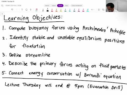
- Justin Tran plans to finish buoyancy and flotation, discuss stability, and introduce Bernoulli’s equation.
- Thursday’s campuswide evacuation drill at 5:00 PM will shorten the in-person lecture by about 15 minutes.
- Homework 2 is due Sunday and is longer than Homework 1; Problem 3 is a former exam problem that can help indicate exam difficulty.
11:19
Homework 2 Problem 2: Effective Area on the L-Shaped Gate
- For the horizontal gate plate, water pressure acts on both its top and bottom, so most opposing forces cancel.
- The uncancelled horizontal-plate force acts only over the area covering the air pipe; do not use the full plate area.
- In Part B, the vertical section—not the horizontal section—is angled at 45°, with water on the gate’s left side.
- For the angled section, adjust the hydrostatic force magnitude, area, and force location.
16:41
Buoyant Force Versus Object Weight
- For a fully submerged object, buoyant force is the surrounding-fluid density times gravity times object volume: ρfluid gV.
- Object weight is calculated using the object’s own density: ρobject gV.
- The net vertical force is gV(ρfluid − ρobject), determining whether the object rises, sinks, or is neutrally balanced.
23:38
Partial Submersion Changes Buoyant Volume, Not Total Weight
- Buoyancy acts only on the submerged portion, so use submerged volume when an object is only partly in the fluid.
- Weight still uses the object’s total volume, whether or not the object is fully submerged.
- Air also produces buoyancy, but its effect is usually negligible compared with water for ordinary calculations.
25:29
How Heating Air Makes a Hot-Air Balloon Rise
- A burner heats the air inside the balloon, lowering its density relative to the colder surrounding air.
- The upward buoyant force depends on cold-air density, while the hot air contributes to the balloon’s weight.
- With buoyancy greater than weight, the balloon rises; for a tethered balloon, rope tension balances the net upward force.
31:12
Life-Jacket Design Requirements and Material Properties
- The design example uses a minimum required supported load of 22 lb under the stated U.S. Coast Guard requirement.
- The foam has a specific weight of 2.0 lb/ft³, while water’s specific weight is 64.0 lb/ft³.
- The jacket’s non-foam components add 1.3 lb, so the foam must support a total downward load of 23.3 lb.
36:15
Calculating the Required Life-Jacket Foam Volume
- The free-body diagram includes upward buoyancy and downward forces from the foam, the 22 lb load, and 1.3 lb of other components.
- Setting the vertical forces to zero gives (64 − 2)V = 23.3, using water and foam specific weights in lb/ft³.
- The required foam volume is 23.3/62 ≈ 0.376 ft³, assuming the jacket is fully submerged.
42:05
Floating-Body Stability and What Happens After a Disturbance
- A floating object can be in equilibrium yet still be unstable: a small breeze or rotation may make it flip.
- Stability depends on the relative positions of the object’s center of gravity and center of buoyancy.
- A restoring moment returns a disturbed object toward its original orientation; an overturning moment drives it farther away.
45:56
Center of Gravity, Center of Buoyancy, and Restoring Moments
- The center of gravity is the effective location of the object’s weight; for uniform-density objects it coincides with the centroid.
- The center of buoyancy is the centroid of the submerged volume, where the buoyant force acts.
- With heavy material low in the object, the weight acts below the buoyant force; a slight rotation creates a restoring moment and stable equilibrium.
52:39
Top-Heavy Floating Objects and Boat Stability
- When an object’s center of gravity is above its center of buoyancy, a small disturbance can create a moment that continues the rotation.
- The object may capsize until it reaches a more stable orientation, even though its undisturbed position initially had no net moment.
- Boat design promotes stability by placing engines and other heavy equipment low in the hull, helping the boat recover in choppy water.
56:17
Bernoulli’s Equation: The Shift from Static to Moving Fluids
- Bernoulli’s equation begins the course’s fluid-dynamics unit, where fluids have velocity and kinetic energy.
- Applications include airflow over an airfoil, environmental wind patterns, and flow through a converging nozzle.
- The equation provides an initial tool for relating fluid velocity and pressure; pressure can also drive fluid from one region to another.
- The unit introduces conservation of mass alongside the energy relationship.
1:03:57
Streamlines Trace Fluid-Particle Paths
- A streamline represents the path a fluid particle follows as it moves with the flow, such as air passing over an airfoil.
- A particle stays on its streamline rather than jumping to a neighboring one.
- At each point, a streamline is tangent to the local fluid-velocity direction.
- Bernoulli’s equation is applied between locations connected along the same streamline.
1:08:36
Bernoulli’s Equation Links Pressure, Speed, and Height
- Between two points on a streamline, P₁ + ½ρu₁² + ρgh₁ = P₂ + ½ρu₂² + ρgh₂.
- The terms represent pressure energy, kinetic energy per unit volume, and gravitational potential energy per unit volume.
- The equation states that their sum remains constant along the streamline under its required assumptions.
1:14:26
Energy Conversion in Bernoulli Flow and the Hydrostatic Limit
- Fluid energy can shift between pressure, kinetic, and gravitational forms while their total remains constant when no external work is added.
- A falling solid converts gravitational potential energy into kinetic energy; Bernoulli describes an analogous balance in flowing fluid.
- Setting velocity to zero removes the kinetic term and recovers the pressure–height relationship used for hydrostatics.
1:17:17
The Four Conditions for Applying Bernoulli’s Equation
- Apply the equation along a streamline, not between arbitrary points that are unconnected by the flow.
- Assume incompressible flow, meaning fluid density is constant, and steady flow, meaning conditions do not change with time.
- Assume inviscid flow, so viscosity effects are negligible; Tran identifies this as a frequently difficult assumption in practical flows.
- Steady does not mean static: a fluid can move with constant conditions over time.
1:21:49
Wind Stagnation Pressure and the Lecture’s Closing Notes
- For wind approaching a face, compare an upstream point with the stagnation point at the face; at equal height, the velocity there falls to zero.
- Bernoulli converts upstream kinetic energy into pressure, giving stagnation pressure as upstream pressure plus ½ρV².
- Tran illustrates the application with a student project that simulated 100 mph wind on a professor’s AI-generated CAD face model.
- The lecture ends with a preview of further Bernoulli examples for Thursday, followed by brief post-class administrative discussion.
Summary, takeaways, and chapters were generated by AI from the video's transcript and may contain errors. The video belongs to its creator, Justin Tran.