EE 330 Lecture 2026/10/06 Ch5 MOS#2
 Watch on YouTube →
Overview
The lecture develops the NMOSFET operating-region model, using threshold voltage VTN and overdrive voltage VOV = VGS − VTN to distinguish cutoff, triode, and saturation. Worked problems apply the region equations and circuit symbols, then extend the ideal saturation model to account for channel-length modulation using Early voltage VA, λ, and output resistance ro; PMOS equations are introduced as a polarity-adjusted counterpart.
Key takeaways
- For an NMOSFET, calculate VOV = VGS − VTN first; the comparison VDS < VOV or VDS ≥ VOV determines triode versus saturation.
- The ideal saturation current is ID = ½KNVOV², so doubling overdrive quadruples current while doubling the boundary voltage VDS = VOV.
- Quadratic solutions must be checked against their assumed region: for VOV ≈ 0.22 V, the 50 μA triode example has a valid root near VDS = 0.06 V because the other root exceeds VOV.
- Channel-length modulation makes practical saturation current rise with VDS; the model ID ≈ ID0(1 + λVDS) uses λ = 1/VA.
- MOSFET output resistance is approximately ro = VA/ID0 and captures the finite slope of the saturation-region ID–VDS curve.
- Most discrete MOSFETs expose three terminals because the body is internally tied to the source, while four-terminal devices allow separate body biasing.
Chapters
0:00
NMOSFET Cutoff, Triode, and Saturation Recap
- An NMOSFET is in cutoff when VGS is below VTN, so drain current ID is approximately zero.
- Define overdrive voltage as VOV = VGS − VTN; it measures the gate voltage available beyond threshold.
- For VGS > VTN, compare VDS with VOV: VDS < VOV is triode, VDS = VOV is the boundary, and VDS > VOV is saturation.
- The ideal saturation equation follows by evaluating the triode current expression at VDS = VOV, producing the one-half factor.
8:00
MOSFET Symbols, Body Connections, and Current Direction
- Three MOSFET symbol conventions are compared; the lecture favors the symbol that clearly indicates conventional drain-current direction.
- The body is also called the substrate; most discrete MOSFETs have three terminals because the body is internally connected to the source.
- Four-terminal MOSFETs expose the body for specialized applications.
- Source and drain are physically symmetric in the basic structure, but packaging and circuit connections assign their roles.
12:49
Visualizing Threshold and the Triode–Saturation Boundary
- A gate-to-source voltage below VTN does not form a conducting channel; exceeding VTN creates channel current.
- The available channel drive is VOV, while the drain-to-source voltage is VDS.
- When VDS is below VOV, the device operates in triode; when VDS reaches or exceeds VOV, it reaches the boundary or saturation.
- The voltage-height sketch illustrates the comparison between gate overdrive and drain voltage.
16:03
Region Conditions and Equivalent Voltage Tests
- For NMOS operation, the key conditions are VGS > VTN and the comparison of VDS with VOV.
- At the triode–saturation boundary, VDS = VOV; saturation requires VDS ≥ VOV.
- Using terminal-voltage relationships, the saturation condition can also be expressed as a gate-to-drain voltage test.
- These equivalent inequalities help verify a region after solving a circuit rather than relying on an assumed operating mode.
23:42
Reading NMOSFET Output and Transfer Curves
- An ID-versus-VDS curve begins near zero current, rises through triode, and levels off at the ideal saturation boundary.
- Increasing VGS raises VOV and produces a higher-current curve; at VGS = VTN, the ideal model predicts no channel current.
- The lecture emphasizes saturation curves because EE 330 focuses on transistor operation for amplification.
- Triode operation remains important for switching applications, including later power-electronics study.
27:25
The Large-Signal MOSFET Controlled-Current Model
- In saturation, the ideal large-signal relation is ID = ½KN′(W/L)VOV².
- The gate-to-source voltage controls drain current, so the MOSFET can be represented as a voltage-controlled current source.
- The model is valid only when VGS > VTN and VDS ≥ VOV.
- This DC large-signal model is distinct from the small-signal amplifier model developed later in the course.
32:07
Calculating MOSFET Process and Device Parameters
- The worked problem uses a 0.18 μm process, W = 2 μm, VTN = 0.5 V, and given mobility and oxide-capacitance values.
- The process parameter is calculated as KN′ = μnCox, approximately 387 μA/V² in the example.
- Combining KN′ with W/L gives KN = KN′(W/L), approximately 4.3 mA/V² for the stated device.
- The calculation highlights unit consistency when converting between microamps and milliamps.
35:19
Solving an NMOSFET at the Saturation Boundary
- For a specified ID = 100 μA, the saturation equation gives VOV of approximately 0.22 V.
- Since VOV = VGS − VTN and VTN = 0.5 V, the example gives VGS ≈ 0.72 V.
- At the boundary, VDS = VOV, so VDS is approximately 0.22 V.
- The negative square-root solution is rejected because it is inconsistent with positive NMOS overdrive and conducting operation.
38:05
Selecting the Valid Triode Solution for Lower Current
- With VGS held at approximately 0.72 V, lowering ID from 100 μA to 50 μA moves the operating point into triode.
- The triode equation, ID = KN[VOVVDS − ½VDS²], yields a quadratic with two positive mathematical roots.
- Only VDS ≈ 0.06 V is physically valid because it satisfies the triode condition VDS < VOV ≈ 0.22 V.
- The other positive root lies outside the region used to derive the triode equation and must be discarded.
43:13
How Doubling Overdrive Changes Boundary Current
- At fixed device dimensions, saturation-boundary current varies with the square of overdrive: ID = ½KNVOV².
- Doubling VOV therefore increases the boundary current by a factor of four.
- Because the boundary condition is VDS = VOV, the boundary drain voltage doubles when VOV doubles.
- The current–voltage curves visualize the shift to a higher-current operating curve.
46:39
Using the Small-VDS Region to Extract KN
- For VDS much smaller than VOV, the MOSFET behaves approximately like a voltage-controlled resistance.
- The small-VDS approximation is ID ≈ KN VOV VDS, so the measured ratio ID/VDS can be used with VOV to determine KN.
- With VOV = 0.5 V and an example resistance of 1 kΩ, the extracted parameter is approximately KN = 2 mA/V².
- This linear-region calculation supplies a device parameter used to evaluate later triode and saturation cases.
53:26
Classifying VDS = 0.2, 0.5, and 1 V Cases
- For the example with VOV = 0.5 V, VDS = 0.2 V is in triode because VDS < VOV.
- At VDS = 0.5 V, the device is on the triode–saturation boundary.
- At VDS = 1 V, it is in saturation because VDS > VOV.
- The appropriate current equation changes with the region: use the triode expression below the boundary and the saturation expression at or above it.
59:31
Channel-Length Modulation Raises Saturation Current
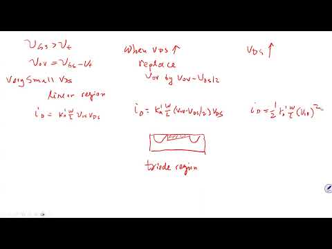
- The ideal channel sketches progress from a nearly rectangular profile in the small-VDS region to a trapezoidal triode profile and a pinched channel in saturation.
- Increasing VDS beyond the saturation boundary moves the pinch-off point toward the source and shortens the effective channel.
- The shorter effective channel causes actual ID to increase with VDS instead of remaining perfectly constant as the ideal model predicts.
- Curves for different overdrive voltages have saturation-region slopes that can be extrapolated to a shared voltage intercept.
1:08:17
Early Voltage, λ, and MOSFET Output Resistance
- The common extrapolated intercept on the VDS axis is the Early voltage VA; the channel-length modulation parameter is λ = 1/VA.
- A practical saturation model is ID ≈ ID0(1 + λVDS), where ID0 is the ideal saturation current.
- The small-signal output resistance is approximated by ro = VA/ID0, equivalently 1/(λID0).
- This non-ideal output resistance is important in later amplifier and small-signal circuit analysis.
1:15:25
Applying Channel-Length Modulation and Introducing PMOS
- In the numerical example, VA′ = 5 V/μm and L = 0.8 μm give VA = 4 V and λ = 0.25 V⁻¹.
- For an increase in VDS from 0.8 V to 1.8 V, the channel-length-modulation factor is evaluated using 1 + λVDS.
- PMOS equations follow the same general method, with polarity handled using absolute values and P-channel parameters such as μp and VTP.
- The lecture closes by noting exam-solution corrections and encouraging students to understand how to apply the equations, not just copy them.
Summary, takeaways, and chapters were generated by AI from the video's transcript and may contain errors. The video belongs to its creator, Wireless Power Transfer.