Dynamics (MIT 16.07) - Lecture 8: Momentum and Euler's Equation
 Watch on YouTube →
Overview
MIT 16.07 develops rigid-body dynamics from inertia and kinetic energy through linear and angular momentum to Euler’s rotational equation. It derives the 3D parallel axis theorem, defines generalized momentum as ∂L/∂q̇, and uses conservation laws to describe free-rotation trajectories geometrically as intersections of a momentum sphere and an energy ellipsoid.
Key takeaways
- For components whose inertia matrices are expressed in a common frame, the composite inertia about the combined center of mass is the sum of each component inertia plus mᵢ[(rᵢᵀrᵢ)I − rᵢrᵢᵀ] for every center-of-mass offset rᵢ.
- Generalized momentum is obtained consistently in any coordinate system from p = ∂L/∂q̇; for a quadratic kinetic energy with mass matrix M(q), it is M(q)q̇.
- Euler’s equation, Jω̇ + ω×Jω = τ, is the rotational counterpart of Newton’s law, with the cross-product term arising when angular momentum is differentiated while expressed in the rotating body frame.
- For torque-free rigid-body motion, angular momentum and kinetic energy are both conserved, confining the body-frame angular-momentum vector to the intersection of a sphere and an ellipsoid.
- A torque-free steady spin occurs when angular momentum aligns with an eigenvector of the inertia tensor; choosing those eigenvectors as coordinates makes J diagonal and defines the principal axes.
Chapters
0:00
Rigid-Body Dynamics: Inertia and the Lecture Roadmap
- Rigid-body models are used for aircraft, satellites, drones, and legged robots.
- A 3×3 inertia matrix plays the rotational role of mass and depends on the coordinate frame.
- Rotational kinetic energy is ½ωᵀJω, so energy depends on the spin axis as well as spin rate.
3:50
Parallel Axis Theorem: Combining Two Rigid-Body Components
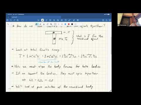
- A composite shape, such as a T made from two rods, can be modeled by combining the components’ masses and inertia matrices.
- Before adding inertia matrices, rotate them into aligned body-frame axes to account for how the components are joined.
- The combined inertia is defined about the new system’s center of mass, not the separate components’ original centers.
10:55
Deriving the 3D Parallel Axis Formula from Kinetic Energy
- Let r₁ and r₂ point from the combined center of mass to the components’ centers of mass; their shared angular velocity gives each component an offset velocity.
- Substituting those velocities into translational kinetic energy produces the offset contributions to rotational inertia.
- The resulting formula is J = J₁ + J₂ + Σmᵢ[(rᵢᵀrᵢ)I − rᵢrᵢᵀ], with each component inertia expressed in the same frame.
17:15
Applying the Inertia Recipe and Checking Its Properties
- The practical sequence is to align body frames, find the combined center of mass, add component inertias, and add the mass-offset terms.
- J must be symmetric positive definite because ½ωᵀJω cannot be negative for any angular velocity.
- The inertia tensor is closely related to the covariance of a mass distribution, and CAD software performs these component calculations internally.
21:00
Generalized Momentum from the Lagrangian
- For a point mass with T = ½mvᵀv, differentiating kinetic energy with respect to velocity gives p = ∂T/∂v = mv.
- For generalized coordinates, momentum is p = ∂L/∂q̇; because potential energy does not depend on q̇, this equals ∂T/∂q̇.
- For a system with T = ½q̇ᵀM(q)q̇, generalized momentum is p = M(q)q̇, which also handles articulated mechanisms and non-Cartesian coordinates.
27:00
Momentum Conservation, Cyclic Coordinates, and Noether’s Theorem
- The Euler–Lagrange equation gives ṗ = ∂L/∂q, so a coordinate absent from L has conserved corresponding momentum.
- Noether’s theorem connects continuous symmetries to conserved quantities: translation symmetry gives linear momentum, and rotational symmetry gives angular momentum.
- Time-translation symmetry corresponds to energy conservation; damping breaks that time-reversal symmetry.
31:00
Linear and Angular Momentum of a Rigid Body
- For a rigid body, translational momentum is p = mv, using center-of-mass velocity in the inertial frame.
- Differentiating rotational kinetic energy with respect to body-frame angular velocity gives angular momentum H = Jω.
- The lecture uses H for angular momentum and keeps rotational quantities in the body frame, where J is constant.
33:30
Deriving Euler’s Equation in the Body Frame
- In the inertial frame, angular momentum obeys dH/dt = τ, the rotational counterpart of Newton’s second law.
- Writing H in the body frame as Jω and differentiating its inertial-frame representation introduces the rotation-matrix derivative Q̇ = Q S(ω).
- Expressing torque and angular acceleration in body coordinates yields Euler’s equation: Jω̇ + ω×(Jω) = τ.
41:15
Newton–Euler Dynamics for Aircraft, Drones, and Robots
- With the body-frame origin at the center of mass, translation and rotation decouple: m v̇ = F and Jω̇ + ω×Jω = τ.
- The combined model uses a mass matrix with mI for translation and J for rotation, plus the rotational velocity-dependent term ω×Jω.
- The same Newton–Euler structure applies to drones, airplanes, spacecraft, underwater vehicles, and legged robots; their force and torque models differ.
45:15
Free-Rotation Lagrangian: Why a Naive Derivation Misses a Term
- For an unforced rotating body, the apparent Lagrangian is just T = ½ωᵀJω.
- Treating ω as a generalized velocity seems to give Jω̇ = 0, which omits Euler’s ω×Jω term.
- The lecture leaves this as a challenge: the missing term is tied to representing rotation in a moving body frame rather than an ordinary fixed-coordinate generalized velocity.
48:15
Torque-Free Rotation and the Momentum Sphere
- With zero external torque, inertial-frame angular momentum is constant, so its magnitude is constant in the rotating body frame as well.
- The body-frame angular-momentum vector H therefore traces a path on a sphere called the momentum sphere.
- Using H = Jω, the torque-free equation can be written Ḣ = H×J⁻¹H; its right-hand side is perpendicular to H, preserving the magnitude.
53:20
Energy Ellipsoid and Geometric Rotation Trajectories
- Torque-free rotation also conserves kinetic energy, E = ½ωᵀJω = ½HᵀJ⁻¹H.
- A fixed value of HᵀJ⁻¹H defines an energy ellipsoid in angular-momentum space; a spherical inertia tensor would make it a sphere.
- Possible H trajectories lie at the intersection of the momentum sphere and energy ellipsoid, revealing qualitative motion without solving the nonlinear ODE.
- The intersections range from fixed-axis spin equilibria to closed paths; these geometric constraints also help check numerical simulations.
59:00
Spin Equilibria and the Principal Axes of Inertia
- A nonzero torque-free equilibrium requires H×J⁻¹H = 0, meaning H is parallel to J⁻¹H and lies along an inertia eigenvector.
- The principal-axis frame aligns its axes with the eigenvectors of J, making the inertia matrix diagonal.
- The diagonal moments are conventionally ordered from smallest to largest and named the minor, intermediate, and major moments of inertia.
Summary, takeaways, and chapters were generated by AI from the video's transcript and may contain errors. The video belongs to its creator, MIT Robotic Exploration Lab.